Table of Contents

Related Manuals for Apogee Instruments SP-420


Summary of Contents for Apogee Instruments SP-420
-
Page 1: Owner's Manual
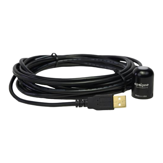
OWNER’S MANUAL USB PYRANOMETER Models SP-420 APOGEE INSTRUMENTS, INC. | 721 WEST 1800 NORTH, LOGAN, UTAH 84321, USA TEL: (435) 792-4700 | FAX: (435) 787-8268 | WEB: APOGEEINSTRUMENTS.COM Copyright © 2020 Apogee Instruments, Inc. -
Page 2: Table Of Contents
TABLE OF CONTENTS Owner’s Manual ....................................1 Certificate of Compliance ................................. 3 Introduction ..................................... 4 Sensor Models ..................................5 Specifications ................................... 6 Deployment and Installation ..............................9 Software Installation ................................10 Operation and Measurement ..............................11 Windows Software ................................. 13 MAC software .................................. -
Page 3: Certificate Of Compliance
RoHS 3 compliant using exemption 6c. Further note that Apogee Instruments does not specifically run any analysis on our raw materials or end products for the presence of these substances, but rely on the information provided to us by our material suppliers. -
Page 4: Introduction
Sensors are potted solid with no internal air space and are designed for continuous total shortwave radiation measurement on a planar surface in outdoor environments. The SP-420 outputs a signal that is directly proportional to total shortwave radiation from the sun. The voltage signal from the sensor is directly proportional to radiation incident on a planar surface (does not have to be horizontal), where the radiation emanates from all angles of a hemisphere. -
Page 5: Sensor Models
SENSOR MODELS This manual covers the USB smart sensor model SP-420. Additional models are covered in their respective manuals. Model Signal SP-420 SP-110 Self-powered SP-230* Self-powered SP-212 0-2.5 V SP-214 4-20 mA SP-215 0-5 V SP-421 SDI-12 SP-422 Modbus Sensor model number and serial number are located near the pigtail leads on the sensor cable. -
Page 6: Specifications
61 mA Calibration Traceability Apogee Instruments SP series pyranometers are calibrated through side-by-side comparison to the mean of four Apogee model SP-110 transfer standard pyranometers (shortwave radiation reference) under high intensity discharge metal halide lamps. The transfer standard pyranometers are calibrated through side-by-side comparison to the mean of at least two ISO-classified reference pyranometers under sunlight (clear sky conditions) in Logan, Utah. - Page 7 Spectral Response Spectral response estimate of Apogee silicon-cell pyranometers. Spectral response was estimated by multiplying the spectral response of the photodiode, diffuser, and adhesive. Spectral response measurements of diffuser and adhesive were made with a spectrometer, and spectral response data for the photodiode were obtained from the manufacturer.
- Page 8 Cosine Response Directional, or cosine, response is defined as the measurement error at a specific angle of radiation incidence. Error for Apogee silicon-cell pyranometers is approximately ± 2 % and ± 5 % at solar zenith angles of 45° and 75°, respectively. Mean cosine response of eleven Apogee silicon-cell pyranometers (error bars represent two standard deviations...
-
Page 9: Deployment And Installation
Mount the sensor to a solid surface with the nylon mounting screw provided. To accurately measure PPFD incident on a horizontal surface, the sensor must be level. An Apogee Instruments model AL-100 Leveling Plate is recommended to level the sensor when used on a flat surface or being mounted to surfaces such as wood. To facilitate mounting on a mast or pipe, the Apogee Instruments model AL-120 Solar Mounting Bracket with Leveling Plate is recommended. -
Page 10: Software Installation
SOFTWARE INSTALLATION The most recent version of ApogeeConnect software can be downloaded at http://www.apogeeinstruments.com/downloads/. Installing the software on a PC (Windows compatible, XP and later) 1. Double click on the installer package: 2. On the ‘Welcome’ screen, please click ‘Next’ to continue. 3. -
Page 11: Operation And Measurement
OPERATION AND MEASUREMENT Spectral Errors for Measurements with Silicon-cell Pyranometers Apogee SP series pyranometers are calibrated under electric lamps in a calibration laboratory. The calibration procedure simulates calibration under clear sky conditions at a solar zenith angle of approximately 45°. However, due to the limited spectral sensitivity of silicon-cell pyranometers compared to the solar radiation spectrum (see graph below), spectral errors occur when measurements are made in conditions that differ from conditions the sensor was calibrated under (e.g., the solar spectrum differs in clear sky and cloudy conditions, thus measurements... - Page 12 Spectral error for Apogee SP series pyranometers as a function of solar zenith angle, assuming calibration at a zenith angle of 45°. Spectral error for Apogee SP series pyranometers as a function of atmospheric air mass, assuming calibration at an air mass of 1.5.
-
Page 13: Windows Software
WINDOWS SOFTWARE When the SP-420 sensor is not plugged into the USB port, the software will display a message in the lower left corner, “Device Not Connected,” indicating it cannot establish communication with the sensor. Plug the sensor into a USB port and allow some time for the sensor to automatically establish communication with the software. - Page 14 Click the ‘Settings’ icon to display the software options. Note ‘Light Source’ is not a setting for the SP- 420. Clicking ‘Calibration’ will display the factory calibrated multiplier and offset values. These values are saved in firmware and can be recovered by clicking the ‘Recover Original’...
- Page 15 Uncover the sensor and wait for the shortwave radiation reading to settle before entering the reference value. Click OK. The multiplier and offset values will automatically calculate and update in the appropriate field. Be sure to click ‘Save’ to retain the new multiplier and offset. Clicking ‘Data Logging’...
- Page 16 ‘Manage Field Logging’ is used to setup the SP-420 for use in the field. When the SP-420 is supplied power from a USB power source it will log data which you can retrieve. Choose the interval that data is saved as well as the interval that data is sampled and the light source used.
- Page 17 Click ‘Erase Data’ to erase all the saved data. This can’t be undone. To use additional SP-420 devices, open additional ApogeeConnect software windows. The device serial number will display in the lower left hand corner of the corresponding software window. Devices may be selected by...
-
Page 18: Mac Software
MAC SOFTWARE When the SP-420 sensor is not plugged into the USB port, the software will display a message in the lower left corner, “Device Not Connected,” indicating it cannot establish communication with the sensor. Plug the sensor into a USB port and allow some time for the sensor to automatically establish communication with the software. - Page 19 Click the ‘Settings’ icon to display the software options. Note ‘Light Source’ is not a setting option for the SP-420. Clicking ‘Calibration’ will display the factory calibrated multiplier and offset values. These values are saved in firmware and can be recovered by clicking the ‘Recover Original’...
- Page 20 The multiplier and offset values will automatically calculate and update in the appropriate field. Be sure to click ‘Save’ to retain the new multiplier and offset. Clicking ‘Data Logging’ will allow the user to log interval measurements in a csv file while the software is open and communicating with the sensor.
- Page 21 ‘Manage Field Logging’ is used to setup the SP-420 for the use in the field. When the SP-420 is supplied power from a USB power source it will log data which you can retrieve. Choose the interval the data is saved as well as the interval that data is sampled and the light source used.
- Page 22 Set the sampling interval in minutes or seconds. The sampling interval is how often a measurement is taken and logging interval is how often the data is saved. The logged data is the average of the samples. The logging interval must be evenly divided by the sampling interval.
- Page 23 Spectral Errors for Shortwave Radiation Measurements with Apogee SP Series Pyranometers Radiation Source (Error Calculated Relative to Sun, Clear Sky) Error [%] Sun (Clear Sky) Sun (Cloudy Sky) Reflected from Grass Canopy 14.6 Reflected from Deciduous Canopy 16.0 Reflected from Conifer Canopy 19.2 Reflected from Agricultural Soil -12.1...
-
Page 24: Maintenance And Recalibration
MAINTENANCE AND RECALIBRATION Moisture or debris on the diffuser is a common cause of low readings. The sensor has a domed diffuser and housing for improved self-cleaning from rainfall, but materials can accumulate on the diffuser (e.g., dust during periods of low rainfall, salt deposits from evaporation of sea spray or sprinkler irrigation water) and partially block the optical path. - Page 25 Homepage of the Clear Sky Calculator. Two calculators are available: One for pyranometers (total shortwave radiation) and one for quantum sensors (photosynthetic photon flux density). Clear Sky Calculator for pyranometers. Site data are input in blue cells in middle of page and an estimate of total shortwave radiation is returned on right-hand side of page.
-
Page 26: Troubleshooting And Customer Support
TROUBLESHOOTING AND CUSTOMER SUPPORT Cable Length Fifteen feet is the maximum cable length that can be built into the sensor. Modifying Cable Length If you required a longer cable length an “active” USB extension cable is required. Please note, the connection between the cables must be made water tight prior to submersion. -
Page 27: Return And Warranty Policy
RETURN AND WARRANTY POLICY RETURN POLICY Apogee Instruments will accept returns within 30 days of purchase as long as the product is in new condition (to be determined by Apogee). Returns are subject to a 10 % restocking fee. WARRANTY POLICY... - Page 28 84321, USA 5. Upon receipt, Apogee Instruments will determine the cause of failure. If the product is found to be defective in terms of operation to the published specifications due to a failure of product materials or craftsmanship, Apogee Instruments will repair or replace the items free of charge.
Need help?
Do you have a question about the SP-420 and is the answer not in the manual?
Questions and answers