Advertisement
Quick Links
Allow 6 - 12 ft of clearance around the perimeter of the swing set area when fully assembled.
OWNER'S MANUAL, ASSEMBLY INSTRUCTIONS, CARE, MAINTENANCE AND USER'S GUIDE
Please read this entire instruction and assembly manual completely before proceeding. You must follow all
safety instructions while using this equipment. The surface area where this swing set is set up must be level and free
of all debris. This set is designed to be anchored into the ground and is not to be set up on any hard surfaces such as
concrete, hardened soil or asphalt. Proper surfacing under and surrounding the set adds to the safety level such as
sand or mulch. Read all cautionary statements on the following pages before using this equipment and save this
instruction manual. DO NOT ALLOW CHILDREN TO PLAY ON THIS GYM SET UNSUPERVISED! CONSTANT
ADULT SUPERVISION IS REQUIRED. Do not use when raining or during any inclement weather (i.e. rain, sleet,
snow, ice, high winds, thunderstorms or lightening). DO NOT ALLOW CHILDREN TO JUMP ON OR CLIMB UP ON
THIS SET'S TOP BAR.
For warranty details and registration see the back page of this manual.
FOLLOW ALL ASSEMBLY INSTRUCTIONS AS WRITTEN IN THIS MANUAL
Please retain sales receipt for warranty purposes. DO NOT RETURN THE SET TO
THE STORE.
If replacement parts or customer service is needed please contact XDP Recreation by email at
service@xdprecreation.com or by calling 1-866-884-0535 between 8:00am and 5:00pm (Eastern Standard Time), Monday - Friday. This
gym is designed to be used safely by up to five (5) children, ages 3 years to 8 years, with weight capacity of 100 lbs per child or total
combined weight limit of 500 lbs for all five (5) children (227kgs). This play gym is designed for backyard use only and is NOT intended
for playgrounds, schools, day care facilities, nurseries or other public places. Follow all assembly instructions carefully and as directed
in this manual. This gym conforms to all safety requirements by ASTM for Home Playground equipment when properly assembled using
the instructions enclosed. Adult assembly is required. Contains small parts. For proper stability and safety this gym set should be
installed with ground anchors.
Anchor Kits can be ordered directly from XDP RECREATION at https://www.xdprecreation.com or by calling
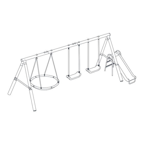
MODEL 98010GW
Aqua Play Park
Assembled dimensions are 148" x 91" x 74"
Important Instructions & Warnings!
1.866.884.0535 or thru your retailer of choice.
0
Advertisement

Related Manuals for XDP Recreation G Series


Summary of Contents for XDP Recreation G Series
- Page 1 Please retain sales receipt for warranty purposes. DO NOT RETURN THE SET TO THE STORE. If replacement parts or customer service is needed please contact XDP Recreation by email at service@xdprecreation.com or by calling 1-866-884-0535 between 8:00am and 5:00pm (Eastern Standard Time), Monday - Friday. This gym is designed to be used safely by up to five (5) children, ages 3 years to 8 years, with weight capacity of 100 lbs per child or total combined weight limit of 500 lbs for all five (5) children (227kgs).
- Page 2 Anchor kit. If you anticipate severe winds, the product should be moved to a sheltered location or completely disassembled. Anchor kits can be ordered directly from XDP RECREATION at https//:www.xdprecreation.com or by calling 1-866-884-0535.
- Page 3 DO NOT install your play set over hard surface, e.g. asphalt, concrete, packed earth, tile or brick floor. A fall onto a hard surface can result in serious injury or death to the user. The following is a list of recommended ground covers from the Consumer Product Safety Commission: SUGGESTED MATERIAL UNCOMPRESSED DEPTH...
- Page 4 PLAY SUPERVISION DO NOT allow more than one child to play on the individual swing or slide component at any one time. DO NOT allow children to stand on the slide, swing seats, trapeze, seesaw, rocky rider, disc swing or glide ride.
- Page 5 INSPECTION PRIOR TO EACH USE OR DAILY INSPECTION DO NOT use the equipment if any bolts or nuts are missing or loose. ALWAYS check to ensure the equipment and all parts are well secured and stable before each use. ...
- Page 6 DO NOT RETURN TO RETAILER WHERE YOU PURCHASED AT. CONTACT XDP FOR PARTS AND SUPPORT AT 1.866.884.0535 or service@xdprecreation.com...
- Page 7 ANCHORING (NOTE: ANCHORS ARE NOT INCLUDED - MUST BE PURCHASED SEPARATELY) There are different ways of anchoring the equipment, depending on the type of ground on which the equipment is to be installed. Make sure that all anchors are below ground level to prevent tripping.
- Page 8 FRAME LEG 12-5/8” CONCRETE 5” 2” BRICK OR GRAVEL BED Note: The maximum fall height for this product is 4 feet. The minimum ground clearance between the bottom of the suspended plays and the playing or ground surface must be 8 inches. You must maintain a minimum of 8 inches of ground clearance.
- Page 9 CARE AND MAINTENANCE CHECKLIST AT THE BEGINNING OF EACH PLAY SEASON: Tighten all hardware. Lubricate all metallic moving parts. Check all protective coverings on bolts, pipes, edges, and corners. Replace if they are loose, cracked, or missing. ...
- Page 10 TOOLS NEEDED Please prepare the following tools prior to assembling this equipment. Special Socket Wrench Tape Measure (Not included) (Not included) Hammer Wrench (If you intend to install anchor, this is needed) (Included) Wrench Medium Allen Wrench (Not Included) (Included) Flat Head and Philips Head Screwdriver Big Allen Wrench (Not included)
- Page 11 Part list for main frame assembly LEFT TOP BAR MIDDLE TOP BAR RIGHT TOP BAR TOP SECTION LEG BOTTOM SECTION LEG WITH FOAM CROSS BAR (WITH TWO HOLES) CROSS BAR (WITH FOUR HOLES) Hardware used for main frame assembly BOLT 5/16” (63MM) BOLT 5/16”...
- Page 12 Part list for swing seat assembly J1-N3 PVC COVERED CHAIN LONG EYE BOLT J3-N3 (PRE-ASSEMBLED ON J1-N3) ONE EYE BOLT WITH ATTACHMENT BOLT J3-N (PRE-ASSEMBLED ON J1-N3) ***The plastic is Ivory Color*** SWING SEAT Hardware used for swing seat assembly NUT 5/16”...
- Page 13 Hardware used for SUPER DISC swing assembly F1-N NUT 5/16” F2-N ARC WASHER 5/16” F3-N PLASTIC CAP (WITH ARC WASHER) Part list for slide assembly X1-N2 SLIDE SUPPORT (WITH OPENING) X2-N2 SLIDE SUPPORT X3-N SLIDE LEG TUBE X4-N SLIDE TOP SUPPORT BAR X5-N SLIDE FRONT SUPPORT SLIDE LADDER STEPS...
- Page 14 Hardware used for slide assembly PLASTIC CONNECTOR BOLT 1/4” (38MM) Z2-N BOLT 1/4” (97MM) SPRING WASHER (LARGE) CAP NUT 1/4” CAP BOLT 1/4” SPRING WASHER (MEDIUM) BOLT 1/4” (75MM) BOLT 1/4” (58MM) Z10-N CROSS FLANGE BOLT 1/4” (20MM) SELF-TAPPING SCREW(10MM) DO NOT RETURN TO RETAILER WHERE YOU PURCHASED AT.
- Page 15 ASSEMBLY INSTRUCTIONS Place the playground equipment on level ground and not less than 6ft (1.8m) from any structure or obstruction such as a fence, garage, house, overhanging branches, laundry line or electrical wires. Do not install the playground equipment over concrete, asphalt, packed earth or any other hard surface;...
- Page 16 STEP 1 – Assemble the top bar frame of the swing set Connect A1, A2 and A3 and secure with B1, B5, B4 and B3 as shown below. Note: All round holes should be facing up and concave holes facing down. NOTE: Do not over-tighten the nuts and bolts at every step.
- Page 17 STEP 2 – Assemble the support legs of swing set Connect A1 to A4 and secure using B1, B5, B4 and B3 as shown below. Repeat this step for the right side of the swing set (A3 and A4). B3 B4 NOTE: Do not over-tighten the nuts and bolts at every step.
- Page 18 STEP 3 – Assemble the support legs of swing set Connect A4 to A5 and secure using B1, B5, B4 and B3 as shown below. Repeat the above step for the right side of the swing set (A3 with A4 & A5). NOTE: Do not over-tighten the nuts and bolts at every step.
- Page 19 STEP 4 – Attach the crossbar to the support legs Attach A6 to the outer side of A4 & A5 and secure using B2, B6, B4 and B3. NOTE: Do not over-tighten the nuts and bolts at every step. 2.
- Page 20 Attach A7 to the outer side of A4 & A5 and secure using B2, B6, B4 and B3. DO NOT RETURN TO RETAILER WHERE YOU PURCHASED AT. CONTACT XDP FOR PARTS AND SUPPORT AT 1.866.884.0535 or service@xdprecreation.com...
- Page 21 STEP 5 - "SWING SEAT" assembly (w. "Adjustable Height" Feature) Important: Please make sure to use the J1-N3 with J3-N (the plastic is Ivory Color). This is CRITICAL to other assembly steps. Connect swing seat to the chains by inserting J3-N3 through K1 and secure with J7, J9 and J6 as shown in Diagram A.
- Page 22 Diagram B J3-N J3-N J1-N3 J1-N3 J3-N3 J3-N3 If you wish to shorten the chain length, follow the below diagram. Diagram C NOTE: Do not over-tighten the nuts and bolts at every step. 2. Do not snap in the cover of plastic cap until you have finished the assembly of each step and went back to tighten all of the nuts and bolts.
- Page 23 STEP 6 – Super Disc swing assembly Separation of foam tube R3-1 from R3-N. Insert the foam tube R3-1 into R4 first, then insert R3-N into R3-1 in R4. Slide the smaller ends of R3-N tubes into the pockets of Super Disc swing fabric (R4).
- Page 24 STEP 7 – Attach Super Disc swing to the swing set frame Connect the chain (R1-N3) to the Super Disc swing by inserting R2B-N3 and securing with F2-N and F1-N as shown in Diagram A. Connect Super Disc swing to the top bar by inserting R2A-N3 through A1 and A2, securing with F3-N and F1-N as shown in Diagram B.
- Page 25 STEP 8 - Slide assembly Connect Y4-1W and Y4-2W and secure with Z10-N (CROSS FLENGE BOLT) and Z6 as shown below. IMPORTANT: Screw in the Z10-N with Z6 onto the middle ridge FIRST. Then screw in the Z10N-N and Z6 onto the side ridges of the slide.
- Page 26 STEP 9 – Hose assembly Insert Y5-B to the hole on the back of Y4-1W. Y5-B Y4-1W hole DO NOT RETURN TO RETAILER WHERE YOU PURCHASED AT. CONTACT XDP FOR PARTS AND SUPPORT AT 1.866.884.0535 or service@xdprecreation.com...
- Page 27 Secure Y5-B with Z11 as shown below. Y5-B NOTE: Please DO NOT hook up the Y5-A HOSE to your water hose until you have finish the COMPLETE assembly of this product. DO NOT RETURN TO RETAILER WHERE YOU PURCHASED AT. CONTACT XDP FOR PARTS AND SUPPORT AT 1.866.884.0535 or service@xdprecreation.com...
- Page 28 STEP 10 - Slide assembly (continued) Insert X5-N into the base of Y4-2W. Secure using Z8, Z6 and Z4. Attach X4-N to Y4-1W. Note: Make sure that the bolt holes face up. Y4-1W Y4-2W X4-N Bolt holes face up. X5-N NOTE: Do not over-tighten the nuts and bolts at every step.
- Page 29 STEP 11 - Slide assembly (continued) Attach X6 to X1-N2 and X2-N2. The inner sides of both X2-N2 and X1-N2, where X6 (slide ladder steps) is attached to, are with concave holes. Secure each side using Z1, Z6 and Z4. ...
- Page 30 STEP 12 - Slide assembly (continued) Secure the two sides of the slide using Z2-N, Z6 and Z4, in the sequence shown in the diagram. Attach X4-N to X1-N2 and X2-N2 and secure using Z1, Z6, Z3 and Z5 as shown in the enlarged diagram.
- Page 31 STEP 13 - Slide assembly (continued) Fit Y1 in between X1-N2 and A7 and secure using Y1, Z7, Z6 and Z3, Z5. X1-N2 NOTE: 1. Do not over-tighten the nuts and bolts at every step. 2. Do not snap in the cover of plastic cap until you have finished the assembly of each step and went back to tighten all of the nuts and bolts.
- Page 32 Congratulations! You have now completed the swing set assembly. Please make sure to thoroughly check all parts and hardware to make sure all bolts and nuts are well secured before using the playground equipment. WARNING - Do not let children use the playground equipment until it is properly assembled and anchored.
- Page 33 What does this Limited Warranty cover? This warranty covers your XDP Recreation product for one hundred and eighty (180) days against defects in material, workmanship, and rust on painted parts which compromise the structural integrity of the product when used for the purpose intended, normal outdoor conditions, and provided it is assembled correctly as illustrated in this manual and receives the proper care and maintenance.
- Page 34 IF NEEDED, GROUND ANCHORS CAN BE BOUGHT FROM THE STORE YOU PURCHASED THIS SET AT OR BY PURCHASING FROM XDP RECREATION'S WEBSITE AT www.xdprecreation.com XDP RECREATION LLC, 5910 SHILOH ROAD EAST, SUITE 108, ALPHARETTA, GEORGIA 30005 REGISTER YOUR “XDP” PURCHASED PRODUCT PLEASE VISIT OUR WEBSITE at www.xdprecreation.com to register your...
- Page 35 Dear Customer, THANK YOU for being an XDP Recreation Customer. IT’S HERE – The NEW TRIPLE FUN-GO ROUND Check out our Website or the General Marketplace For this TRIPLE FUN TRIPLE FUN-GO ROUND - You can ADD to your current swing.
- Page 36 IT’S HERE – The NEW FIREFLY LED SWING Check out our Website or the General Marketplace For this FANTASTICALLY / FUN STROBING – LED – COLORED – FLASHING MODES SWING www.xdprecreation.com KEEP HAVING FUN! www.xdprecreation.com Alpharetta, Georgia 30005, USA DO NOT RETURN TO RETAILER WHERE YOU PURCHASED AT. CONTACT XDP FOR PARTS AND SUPPORT AT 1.866.884.0535 or service@xdprecreation.com...
Need help?
Do you have a question about the G Series and is the answer not in the manual?
Questions and answers