
Subscribe to Our Youtube Channel
Related Manuals for Endress+Hauser RNF22


Summary of Contents for Endress+Hauser RNF22
- Page 1 Products Solutions Services BA02039K/09/EN/01.20 71526787 2020-10-30 Operating Instructions RNF22 Power and error message module 24 V DC...
-
Page 2: Table Of Contents
12.12 Certificates and approvals ....Product description RNF22 ....7 12.13 Supplementary documentation ... . 24... -
Page 3: About This Document
RNF22 About this document About this document Document function These Operating Instructions contain all the information that is required in various phases of the life cycle of the device: from product identification, incoming acceptance and storage, to mounting, connection, operation and commissioning through to troubleshooting, maintenance and disposal. - Page 4 About this document RNF22 1.2.3 Electrical symbols Direct current Alternating current Direct current and alternating current Ground connection A grounded terminal which, as far as the operator is concerned, is grounded via a grounding system. 1.2.4 Symbols in graphics 1, 2, 3,...
-
Page 5: Basic Safety Instructions
RNF22 Basic safety instructions Basic safety instructions Requirements for the personnel The personnel for installation, commissioning, diagnostics and maintenance must fulfill the following requirements: ‣ Trained, qualified specialists must have a relevant qualification for this specific function and task. ‣... -
Page 6: Product Safety
Basic safety instructions RNF22 Hazardous area To eliminate danger to persons or the facility when the device is used in the hazardous area (e.g. explosion protection): ‣ Check the nameplate to verify if the device ordered can be put to its intended use in the hazardous area. -
Page 7: Product Descriptions
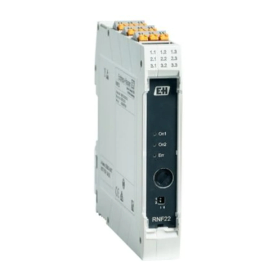
Product design Power and error message module • The RNF22 power and error message module is used to provide the supply voltage to the DIN rail bus connector. Via a relay contact and a flashing LED, the integrated error analysis function signals a power supply failure/fuse error and a group error of the RLN22 Namur modules that are connected via the DIN rail bus connectors. -
Page 8: Scope Of Delivery
Firmware version and device revision Approval logos 2 lines for the TAG name 4.2.2 Name and address of manufacturer Name of manufacturer: Endress+Hauser Wetzer GmbH + Co. KG Address of manufacturer: Obere Wank 1, D-87484 Nesselwang Model/type reference: RNF22 Scope of delivery The scope of delivery comprises: •... -
Page 9: Installation
RNF22 Installation Installation Installation conditions 5.1.1 Dimensions The dimensions of the device are provided in the ' T echnical data' section of the Operating Instructions. 5.1.2 Mounting location The device is designed for installation on 35 mm (1.38 in) DIN rails in accordance with IEC 60715 (TH35). -
Page 10: Disassembling The Din Rail Device
Installation RNF22 A0041736 3 Installing on DIN rail 1. Position the top DIN rail groove at the top end of the DIN rail. 2. While holding the front of the device horizontally, lower it until you hear the locking clip of the device click into place on the DIN rail. -
Page 11: Electrical Connection
RNF22 Electrical connection Electrical connection Electrical connection 6.1.1 Connection conditions A flat-blade screwdriver is required to establish an electrical connection to screw or push- in terminals. AWG 24-14 AWG 24-14 0,2 -2,5 mm ² 0,2 - ,5 mm ² (0,39") 7 mm (0,28") - Page 12 2: LF activated A0042592 6 RNF22 terminal assignment: power and error message module 6.1.3 Power supply The power can be supplied via terminals 1.1 and 1.2 for PWR1 or 2.1 and 2.2 for PWR2. NOTICE The tapping of energy from the DIN rail bus connector for further distribution is not permitted.
-
Page 13: Operation Options
All DIP switches are set to the "II" position when the device is delivered from the factory. The following settings are made via the DIP switches: • Switch off error message when RNF22 Feed-In Module is only supplied by one power supply system (DIP 1) •... -
Page 14: Switching On The Device
Commissioning RNF22 NOTICE ‣ Before commissioning the device, make sure that the supply voltage matches the voltage specifications on the nameplate. Failure to perform these checks may result in damage to the device caused by the incorrect supply voltage. Switching on the device Switch on supply voltage. -
Page 15: Diagnostics And Troubleshooting
RNF22 Diagnostics and troubleshooting Diagnostics and troubleshooting General troubleshooting Always start troubleshooting with the checklists below if faults occur after startup or during operation. The checklists take you directly (via various queries) to the cause of the problem and the appropriate remedial measures. -
Page 16: Return
Repair RNF22 11.3 Return The requirements for safe device return can vary depending on the device type and national legislation. 1. Refer to the website for more information: http://www.endress.com/support/return-material 2. Return the device if repairs or a factory calibration are required, or if the wrong device was ordered or delivered. -
Page 17: Technical Data
Product design Power and error message module • The RNF22 power and error message module is used to provide the supply voltage to the DIN rail bus connector. Via a relay contact and a flashing LED, the integrated error analysis function signals a power supply failure/fuse error and a group error of the RLN22 Namur modules that are connected via the DIN rail bus connectors. -
Page 18: Power Supply
2: LF activated deactivated A0042592 8 RNF22 terminal assignment: power and error message module Terminal assignment Special connection instructions • Disconnecting units and auxiliary circuit protective systems with suitable AC or DC values must be provided in the building installation. -
Page 19: Performance Characteristics
RNF22 Technical data AWG 24-14 AWG 24-14 0,2 -2,5 mm ² 0,2 - ,5 mm ² (0,39") 7 mm (0,28") 0,5-0,6 Nm 5-7 lb In A0040201 9 Electrical connection using screw terminals (left) and push-in terminals (right) Terminal design... -
Page 20: Environment
Technical data RNF22 A0041736 10 Installing on DIN rail 1. Position the top DIN rail groove at the top end of the DIN rail. 2. While holding the front of the device horizontally, lower it until you hear the locking clip of the device click into place on the DIN rail. -
Page 21: Mechanical Construction
RNF22 Technical data 12.8 Mechanical construction Design, dimensions Dimensions in mm (in) Terminal housing for mounting on DIN rail A0044417 Width (B) x length (L) x height (H) (with terminals): 17.5 mm (0.69 in) x 116 mm (4.57 in) x 107.5 mm (4.23 in) -
Page 22: Display And Operating Elements Rnf22
All DIP switches are set to the "II" position when the device is delivered from the factory. The following settings are made via the DIP switches: • Switch off error message when RNF22 Feed-In Module is only supplied by one power supply system (DIP 1) •... -
Page 23: 12.11 Accessories
Various accessories, which can be ordered with the device or subsequently from Endress +Hauser, are available for the device. Detailed information on the order code in question is available from your local Endress+Hauser sales center or on the product page of the Endress+Hauser website: www.endress.com. -
Page 24: 12.13 Supplementary Documentation
• W@M Device Viewer (www.endress.com/deviceviewer): Enter the serial number from nameplate • Endress+Hauser Operations App: Enter the serial number from the nameplate or scan the 2D matrix code (QR code) on the nameplate Brief Operating Instructions Guide that takes you quickly to the 1st measured value... -
Page 25: Appendix: System Overview Of Rn
This eliminates the need for complex and time-consuming single wiring. One way to power several devices is to use the RNF22 power and error message modules, which also offer short-circuit and line break detection. These modules also enable redundant power feed-in where necessary. - Page 26 Appendix: system overview of RN Series RNF22 1.1 1.2 1.1 1.2 1.1 1.2 1.1 1.2 1.1 1.2 1.1 1.2 1.1 1.2 2.1 2.2 2.1 2.2 2.1 2.2 2.1 2.2 2.1 2.2 3.1 3.2 3.1 3.2 3.1 3.2 3.1 3.2 3.1 3.2 3.1 3.2...
- Page 27 • Group error message, line or short-circuit monitoring of side-by-side RLN22 NAMUR isolating amplifiers RNF22 power modules are particularly suitable for supplying power to RNx22 devices. Here, a total current of 3.75 A can be realized. These modules also offer the additional advantage of integrated error evaluation.
- Page 28 · I + ... module1 module2 If power feed-in is via the RNF22 power modules, power can be supplied by a single RNB22 power supply. Alternatively, redundant power feed-in by two different power supplies is also possible. 13.1.5 Power supply via the RNB22 system power supply and RNF22...
- Page 29 RNB22 at 60 °C ambient temperature and less than the maximum permitted current of the RNF22 power module (max. 3 750 mA). To ensure a redundant power supply and to guarantee that the fuse integrated in the RNF22 trips in the event of a short-circuit, the 24 V power is supplied in this example by two RNB22 power supplies 2.5 A / 24 V...
- Page 30 + ... module1 module2 Power feed-in via two RNF22 power and error modules 2 · RNB22 + 2 · RNF22: 2 · 3.15 A (static boost) -> 6 A (at Ta = 40 °C) Formula: I · I · I + ...
-
Page 31: Applications Of The Rn Series Devices
• Supply of electrical power to connected sensors • Line monitoring The devices for these tasks are collectively known as isolating amplifiers or signal isolators and are available with different functions in the Endress+Hauser RN Series. Different types of signals are conditioned in this context. 13.2.1... - Page 32 Appendix: system overview of RN Series RNF22 I (mA) A0045578 16 Modulated HART signal Analog signal Digital signal NAMUR sensors are operated with a transmitted current and have four states so that sensor errors can also be detected by an analog evaluation unit. This is sometimes referred to as the "closed circuit current principle".
- Page 33 RNF22 Appendix: system overview of RN Series Setting up of transmitter via HART communication Commubox FXA195 RN22 PMP71B 0/4…20 mA 0/4…20 mA Output Input (active) (active) Power supply 24 V DC A0045579 17 Pressure measurement in a hazardous area with an RN22 active barrier Please note: the devices have an active and passive current input to which a 2-wire or 4- wire transmitter can be directly connected.
- Page 34 Appendix: system overview of RN Series RNF22 Example: flow measurement in a hazardous area – signal doubling • The passive 2-wire Prowirl F200 sensor supplies a current signal, which is proportional to the flow, to the active input of the isolating amplifier •...
- Page 35 • Line breaks or short-circuits of the 2-wire sensor line are indicated by LEDs on the RLN22, and - if the DIN rail bus connector is used - are reported as a group error message to the RNF22 power and error message module. At the same time, the output relay de-energizes to the currentless state.
- Page 36 Appendix: system overview of RN Series RNF22 FTE20 RLN22 Resistive coupler Output Input (binary) (1.2 or 2.1 mA) Fault Power supply 24 V DC signal A0045583 21 NAMUR limit detection with FTE20 paddle switch with line monitoring in the hazardous area...
- Page 37 RNF22 Appendix: system overview of RN Series Control valve RNO22 0/4…20 mA 0/4…20 mA Output Input (active) (passive) Power supply 24 V DC A0045585 23 Control valve activation in the hazardous area with an RNO22 output isolating amplifier Endress+Hauser...
-
Page 38: Index
Index RNF22 Index Accessories Device-specific ......23 CE mark ........6 Declaration of Conformity . - Page 40 *71526787* 71526787 www.addresses.endress.com...
Need help?
Do you have a question about the RNF22 and is the answer not in the manual?
Questions and answers