Table of Contents
Advertisement
Quick Links
Advertisement
Table of Contents

Related Manuals for Endress+Hauser analytikjena TOC module


Summary of Contents for Endress+Hauser analytikjena TOC module
- Page 1 Operating Manual TOC module...
- Page 2 Analytik Jena AG Manufacturer Konrad-Zuse-Str.1 07745 Jena Germany Phone + 49 3641 / 77 70 + 49 3641 / 77 92 79 Email info@analytik-jena.de Analytik Jena AG Service Konrad-Zuse-Str. 1 07745 Jena Germany Phone + 49 3641 / 77-7407 (Hotline) Email service@analytik-jena.de http://www.analytik-jena.com...
-
Page 3: Table Of Contents
Table of Contents Table of Contents Basic information ..............1 User manual notes ................. 1 Application ..................... 2 Proper use ..................... 2 Warranty and liability ................2 Scope of delivery ................... 3 Technical data ................ 4 Safety instructions ..............5 General notes .................. - Page 4 Table of Contents 4.1.6 Detector ....................15 4.1.7 Indicator and control elements, connectors .......... 15 4.1.7.1 LED displays ..................15 4.1.7.2 Equipment switch, interfaces ..............15 4.1.7.3 Gas connectors ..................18 4.1.7.4 Connector for waste ................18 Function ....................19 Measuring method ................
- Page 5 Table of Contents General information ................30 Equipment faults and analytical problems ..........30 Maintenance and care ............33 Service intervals ................... 33 Replacing the water traps ..............34 Replacing the halogen trap ..............35 Exchanging the catalyst ............... 36 9.4.1 Lifetime of the catalyst .................
- Page 6 Index of Figures Index of Figures Front view, TOC module – Door open ............ 9 Fig. 1 Fig. 2 View of the basic module, left door open ..........10 Fig. 3 TOC combustion tube ................11 Fig. 4 Tube holder for TOC combustion tube ..........11 Fig.
-
Page 7: Basic Information
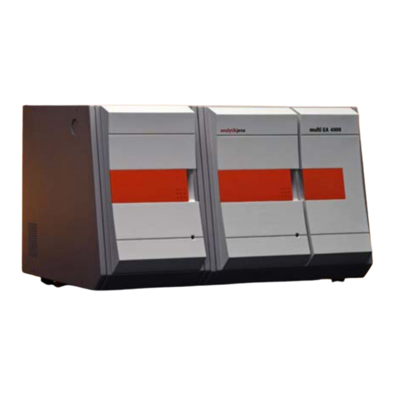
Basic information Basic information User manual notes ® The TOC module is a system module of the modular analyzers multi EA 5000 or ® multi X 2500. It can only be used in combination with one of the two basic modules. The control of the modules and the analysis of the measurements is performed with the ®... -
Page 8: Application
Basic information Application ® ® The expansion of the multi EA 5000 or the multi X 2500 with the TOC module enables the determination of the carbon content in aqueous samples by digestion with the aid of thermocatalytic high-temperature oxidation in the presence of special catalysts according to national and international standards. -
Page 9: Scope Of Delivery
Basic information Scope of delivery IMPORTANT The scope of delivery is listed in the table below for information purposes. Completeness is not guaranteed. Modifications are reserved. When checking the delivered components always refer to the current packing list included in the scope of delivery. Name TOC module, pre-assembled Mains cable... -
Page 10: Technical Data
Technical data Technical data General characteristics Designation/type TOC module Basic device dimensions (W x H x D) approx. (300 x 470 x 530) mm Weight approx. 10 kg Procedural data Digestion principle Thermocatalytic oxidation Digestion temperature 700 °C (Pt/Al2O3) up to 900 °C, depending on the catalyst Detection NDIR (Non-dispersive infra red absorption) 0 –... -
Page 11: Safety Instructions
Safety instructions Safety instructions General notes IMPORTANT This user manual is only valid in conjunction with the following documents: – User manual multi EA ® ® 5000 or multi X 2500 (basic module) – Software manual of the control and analysis software multiWin® Observe in particular the notes in the chapter "Safety notes"... -
Page 12: Safety Instructions - Operation
Safety instructions 3.2.2 Safety instructions - operation The operator of the analyzer with TOC module is obligated to assure that the condition of the devices including the safety equipment is correct before startup. This especially applies after each modification and extension or all repair work. The following has to be observed: ... -
Page 13: Handling Of Auxiliary And Operating Materials
Safety instructions 3.2.5 Handling of auxiliary and operating materials The operator is responsible for the selection of substances used in the process as well as for their safe handling. This is particularly important for radioactive, infectious, poisonous, corrosive, combustible, explosive and otherwise dangerous substances. When handling dangerous substances local safety codes and guidelines must be observed. -
Page 14: Behavior During Emergencies
Safety instructions 3.2.6 Behavior during emergencies The TOC module has to be switched off on the power switch (on the back of the enclosure) and the power supply has to be disconnected from the mains if there are any dangerous situations or accidents. Because a rapid response can save lives during an emergency, the following has to be ensured: ... -
Page 15: Technical Description
Technical description Technical description System design 4.1.1 Overview The TOC module is a detection module for the modular analyzers ® ® multi EA 5000 or multi X 2500. All components of the TOC module which have to be operated or serviced by the operator are accessible via the door on the front side of the module and via the front doors or the covers on the basic module. -
Page 16: Combustion Tube
Technical description Arrangement of the components in the basic module Fig. 2 View of the basic module, left door open Injection port combustion tube Condensation coil Spherical joint, fixated with a fork type clamp 4.1.2 Combustion tube The combustion tube (reactor) consists of quartz glass (refer to Fig. 3). It is filled with catalyst and auxiliary material (refer to Fig. -
Page 17: Sample Preparation
Technical description Fig. 3 TOC combustion tube Screw cap with septum (injection port) Connector oxygen gas supply, hose No. 3 of the basic module Connector condensation coil Fig. 4 Tube holder for TOC combustion tube 4.1.3 Sample preparation Sample feed is performed directly with microliter syringes. A calibrated syringe is used for manual dosing. -
Page 18: Sample Preparation In The Toc Combustion Tube
Technical description 4.1.3.1 Sample preparation in the TOC combustion tube The injection of the aqueous samples into the combustion system is performed via the injection port of the TOC combustion tube (refer to 1 in Fig. 3). This can be done manually or with the Multi Matrix autosampler (TC or NPOC). -
Page 19: Water Traps
Technical description For the TIC determination, 40 % phosphoric acid is placed into the TIC reactor. The dosing of the acid as well as the sample is performed via the front lateral connector with the septum port (refer to chapter 9.5 for the regeneration of the TIC reactor). The analyte gas is guided via the top connector in the direction of the water traps from the TIC condensation vessel. -
Page 20: Connection Method
Technical description Fig. 6 Hose diagram TOC module 4.1.5.2 Connection method So called FAST connectors (as angled adapter and straight adapter) are used in the TOC module for the connection of the hose connections. They guarantee simple handling and operation without gas leakage. IMPORTANT for angled adapters: Make that the hose ends are not pushed over the leg length so that an... -
Page 21: Condensate Pump
Technical description 4.1.5.3 Condensate pump The condensate pump (refer to 4 in Fig. 1) is used to drain condensate or the waste agent from the TIC determination. 4.1.6 Detector The NDIR detector (Non-dispersive infra red absorption detector) is located at the back of the TOC module. - Page 22 Technical description 2 in Fig. 7 ® ® Connection to the basic module multi EA 5000 or multi X 2500 (connector 25-pin interface cable) Name on the TOC module Name on the basic module external external 3 in Fig. 7 Connector socket (25-pin) –...
-
Page 23: Fig. 7 Equipment Backplate
Technical description Fig. 7 Equipment backplate Connector 9-pin interface cable – Hose No. 82 C-NDIR Waste outlet – waste Connector 25-pin interface cable – Power switch, equipment fuse and mains external in supply Connection socket (25-pin) – external out NPOC blow out line – hose from " out ABD " of Analyte gas outlet –... -
Page 24: Gas Connectors
Technical description 4.1.7.3 Gas connectors Application as TOC module Hoses for TOC measurements are connected to the module in the factory (refer to Fig. 7). The hose No. 82 (refer to Fig. 6 and Fig. 7) is connected with the analyte gas inlet "sample in"... -
Page 25: Function
Technical description Function ® ® The expansion of the multi EA 5000 (basic module) or the multi X 2500 with the TOC module enables the determination of the carbon content in aqueous samples. ® The digestion is performed in the basic module of the multi EA 5000 or the ®... -
Page 26: Toc Analysis
Technical description 4.3.2 TOC analysis During the TOC analysis the total organic carbon content of a sample is detected. The TOC determination in the analyzer is performed according to the differential method, which can be described with the following equation: TOC = TC - TIC TOC …... -
Page 27: Transport And Storage
Transport and storage Transport and storage Transport 5.1.1 Preparation of the TOC module for transport WARNING When removing glass components there is a risk of injury from broken glass! Remove the glass components carefully from the TOC module! CAUTION Unsuitable packaging material and residue of measuring solution and chemicals can damage individual components of the TOC module! Only transport the TOC module in its original packaging! Ensure that the module is fully drained and all transport locks have been fitted! -
Page 28: Moving The Toc Module In The Laboratory
Transport and storage 5.1.3 Moving the TOC module in the laboratory WARNING Falling out of loose parts as well as unintentional dropping of the TOC module creates a risk of injury and damage to the module. Remove all loose components from the TOC module before moving the module! Move the TOC module with great care! Securely hold the TOC module with both hands from below! When moving the TOC module in the laboratory observe the following:... -
Page 29: Recommissioning After Transport Or Storage
Transport and storage Recommissioning after transport or storage 5.3.1 Assembling the components When installing the TOC module observe the notes in chapter 6.1. Assemble the components of the TOC module as follows: 1. Carefully remove the TOC module and accessories from the transport packaging. -
Page 30: Connecting The Toc Module
Transport and storage 5.3.2 Connecting the TOC module WARNING The TOC module must always be switched off during connection to the mains supply and to the basic module! Before connecting the mains cable ensure that the equipment switch on the back of the equipment is set to "0"! CAUTION Settled condensation and temperature differences can damage individual... -
Page 31: First Commissioning
First commissioning First commissioning Site requirements 6.1.1 Installation conditions The following requirements are placed on the climatic conditions in the operating room of the TOC module: Temperature range: +10 °C to +35 °C Max. humidity: 90% at 30 °C ... -
Page 32: Energy Supply
First commissioning 6.1.3 Energy supply CAUTION The TOC module must only be connected to a properly grounded mains outlet in accordance with the voltage specifications on the type plate. The TOC module is operated on single-phase alternating current. The installation of the electrical equipment of the laboratory must comply with the standard DIN VDE 0100. -
Page 33: Operation
Operation Operation Basic information The TOC module can only be operated in combination with the basic module ® ® ® multi EA 5000 or multi X 2500. Consult the user manual multi EA 5000 or ® ® multi X 2500 as well as the manual of the control and analysis software multiWin the operation of the TOC module. -
Page 34: Standard Commissioning
Operation 7.2.1 Standard commissioning WARNING Concentrated phosphoric acid is required for the measurement process! The contact with phosphoric acid can cause severe skin and eye injuries! Always wear goggles and protective gloves when handling concentrated phosphoric acid! CAUTION Damages to the optic and electronic components (detectors, flow sensors) due to aggressive combustion products when the cooper wool in the halogen trap is depleted! Replace all of the filling in the halogen trap when half of the copper wool or the measurement wool is visibly discolored! -
Page 35: Performing Measurements
Operation Performing measurements IMPORTANT For each injection a maximum of 500 μl measurement substance may be injected. Inject the sample only after the prompt by the control and evaluation software and in the stated intervals! Always ensure that the volume set in the method is injected! Perform the measurement as follows: 1. -
Page 36: Fault Removal
Fault removal Fault removal General information IMPORTANT If faults cannot be remedied by the customer, the Analytik Jena AG service department must always be informed. This also applies for the repeated occurrence of individual faults. For the fault diagnosis the respective files must be sent by email to the Analytik Jena AG service department (refer to the software manual for the control and evaluation ®... - Page 37 Fault removal Sensitive samples Prevent insertion of CO2 or organic vapors from ambient air Aerate the head room of the sample container for manual measurements Check the environmental conditions Remove the source of interference Drift NDIR basic Check the settings unsuitable integration criteria Increase the maximum integration time Measurement is cancelled to early...
- Page 38 Fault removal Flush carefully with ultrapure water Fill the syringe with 0.1 N HCl Soak time: 10 min Flush carefully with ultrapure water Leaking condensate pump Cause Remedy Leaking hose connections Replace the pump hose Defect pump hose Edition 01/2010 TOC MODULE...
-
Page 39: Maintenance And Care
Maintenance and care Maintenance and care Service intervals TOC module Service task Service interval Clean and maintain the device weekly Check all screw connections for tight fit weekly Check fastening screws for tight fit monthly Water traps Service task Service interval Check gas flow daily Exchange water trap... -
Page 40: Replacing The Water Traps
Maintenance and care Condensation coil Service task Service interval Check for cracks and damages 3 month Clean the condensation coil as required, but no later than after 12 months Condensate pump Service task Service interval Check for leaks 3 month Replace porous pump hose as required, but no later than after 12 months... -
Page 41: Replacing The Halogen Trap
Maintenance and care The label "INLET" on the large water trap (TC prefilter) has to face down and the red label on the small water trap (disposable retention filter) has to face up. 4. Insert the new water traps into the clamps. Note: The large water trap has to be positioned below. -
Page 42: Exchanging The Catalyst
Maintenance and care Exchanging the catalyst 9.4.1 Lifetime of the catalyst If the effectiveness of the catalyst decreases, the combustion tube has to be filled again. A check has to be performed after expiry of the service interval (maximum 1500 ®... -
Page 43: Filling The Combustion Tube
Maintenance and care 9.4.3 Filling the combustion tube CAUTION Alkaline salts (hand perspiration) causes crystallization in the quartz glass when heating combustion tubes in the combustion furnace. This shortens the lifetime of the combustion tube. Avoid touching the cleaned combustion tube with your hand during filling. Wear protective gloves during the filling of the combustion tube. -
Page 44: Inserting The Combustion Tube
Maintenance and care Fig. 8 TOC combustion tube, filled Quartz wool Catalyst Quartz wool Quartz glass fragments HT mat 9.4.4 Inserting the combustion tube Insert the combustion tube as follows: 1. Screw the screw cap with the septum onto the combustion tube. 2. -
Page 45: Regenerating The Tic Reactor
Maintenance and care 8. Switch on the gas supply, insert the mains plug into the power socket and switch on the analyzer on the main switch. 9. Check the system for tightness (refer to chapter 9.10). CAUTION The catalyst can outgas during the first heating (fog formation in the condensation vessel). -
Page 46: Cleaning The Tc Condensation Vessel
Maintenance and care Cleaning the TC condensation vessel WARNING The TIC vessel contains phosphoric acid! Phosphoric acid is irritating for eyes, skin and the mucous membrane! Always wear goggles and protective gloves when handling concentrated phosphoric acid! Rinse the affected skin with water immediately! Visually check the condensation vessel at regular intervals (e.g. -
Page 47: Removing And Installing The Condensation Coil
Maintenance and care Removing and installing the condensation coil 9.7.1 Removing and cleaning the condensation coil Remove the condensation coil in the basic module as follows: 1. Open the doors of the basic module. 2. Undo the knurled screw on the fork type clamp that connects the exit of the combustion tube with the condensation coil. -
Page 48: Removing And Replacing The Pump Hose
Maintenance and care Removing and replacing the pump hose WARNING The pump hose contains phosphoric acid! Phosphoric acid is irritating for eyes, skin and the mucous membrane! Always wear goggles and protective gloves when handling concentrated phosphoric acid! Rinse the affected skin with water immediately. Check the condensate pump every 3 month or after each catalyst change for tightness. -
Page 49: Checking The System For Tightness
Maintenance and care 9.10 Checking the system for tightness The system is checked for tightness (gas line from the inlet of the basic module to the outlet of the TOC module) as follows: 1. The basic module and the TOC module are switched on and connected. 2. -
Page 50: Exchanging The Septums
Maintenance and care 9.11 Exchanging the septums The septums have to be exchanged at regular intervals. A change is required when the tightness of the system is not ensured anymore. The septum of the injection port of the TOC combustion tube should be exchanged during catalyst change or as required. -
Page 51: Spare Part List
Maintenance and care 9.12 Spare part list IMPORTANT The following table contains information on some standard spare parts and consumables. Completeness is not guaranteed. Modifications are reserved. When ordering spare parts or consumables always refer to the current price lists. Name Item number... -
Page 52: Notes On Ordering
Maintenance and care 9.13 Notes on ordering Please send spare part and consumable orders to the following service address. State the item number, spare part name and quantity. Service address: Analytik Jena AG Konrad-Zuse-Str. 1 D-07745 Jena Phone: (00 49 36 41) 77-70 Fax: (00 49 36 41) 77-9272 Email: service@analytik-jena.de... -
Page 53: Waste Disposal
Waste disposal Waste disposal 10.1 Waste water ENVIRONMENTAL PROTECTION The neutralized waste must be brought to the appropriate waste disposal center for correct disposal according to the appropriate legal guidelines. Waste water is created during the analysis operation with the TOC module. This water contains hydrochloric acid, diluted phosphoric acid and sample, depending on the measurement mode.
Need help?
Do you have a question about the analytikjena TOC module and is the answer not in the manual?
Questions and answers