Endress+Hauser Tankvision NXA820 Installation Instructions Manual
Inventory control
Hide thumbs
Also See for Tankvision NXA820:
- Operating instructions manual (28 pages) ,
- Operating instructions manual (76 pages) ,
- Operating instructions manual (44 pages)

Related Manuals for Endress+Hauser Tankvision NXA820


Summary of Contents for Endress+Hauser Tankvision NXA820
- Page 1 Installation Instructions Tankvision NXA820, NXA821, NXA822 Inventory Control BA340F/00/en/04.08...
-
Page 3: Table Of Contents
Table of Contents Table of Contents Safety Instructions ....4 Designated use ......4 Installation, commissioning, operation . -
Page 4: Safety Instructions
It is ideally suited for small tank farms with only a couple of tanks, but also for large refineries with hundreds of tanks. Tankvision consists of the following components: • Tankvision NXA820 (Tank Scanner) scans parameters from tank gauges and performs tank calculations • Tankvision NXA821 (Data Concentrator) summarizes data from various Tank Scanners NXA820 •... -
Page 5: Notes On Safety Conventions And Symbols
Safety Instructions Notes on safety conventions and symbols In order to highlight safety-relevant or alternative operating procedures in the manual, the following conventions have been used, each indicated by a corresponding symbol in the margin. Safety conventions Warning! A warning highlights actions or procedures which, if not performed correctly, will lead to personal injury, a safety hazard or destruction of the instrument "... -
Page 6: Identification
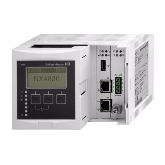
Identification Identification Nameplate Made in Germany D-79689 Maulburg Tankvision Order Code: Ser.-No.: 100 (Auto-MDIX) MAC: 100 (Auto-MDIX) MAC: 250002393-- L00-NXA82xxx-18-00-00-yy-001 1: Order code according to the product structure 2: Serial number 3: Supply voltage 4: Type of fieldbus communication (only for Tank Scanner NXA820) 5: Degree of protection 6: Admissible ambient temperature 7: MAC address of the System LAN port... -
Page 7: Product Structure
Identification Product Structure 2.2.1 Tank Scanner NXA820 Approval Non-hazardous area Field Communication; Input Sakura V1 protocol, max. 10 instruments Whessoematic 550, max. 15 instruments (in preparation) Modbus EIA485 master, max. 15 instruments Special version, to be specified Power supply 90-250 VAC 50/60Hz 10.5-32 VDC Special version, to be specified Inventory calculations... - Page 8 Identification 2.2.2 Data Concentrator NXA821 Approval Non-Hazardous area Power supply 90-250 VAC 50/60Hz 10.5-32 VDC Special version, to be specified Data Archive Memory Size 1GB; 15 parameters/min; 90 days Special version, to be specified Local Operation status display Special version, to be specified Operation Language English Special version, to be specified...
- Page 9 Identification 2.2.3 Host Link NXA822 Approval Non-hazardous area Communication; Output Modbus serial, / TCP/IP slave interface Special version, to be specified Power Supply 90-250 VAC 50/60Hz 10.5-32 V DC (in preparation) Special version, to be specified Local Operation status display Special version, to be specified Operating language English...
-
Page 10: Supplied Documentation
The device complies with the applicable standards and regulations as listed in the EC declaration of conformity and thus complies with the statutory requirements of the EG directives. Endress+Hauser confirms the successful testing of the device by affixing to it the CE mark. -
Page 11: Installation
Installation Installation Incoming acceptance, transport, storage 3.1.1 Incoming acceptance Check the packing and contents for any signs of damage. Check the shipment, make sure nothing is missing and that the scope of supply matches your order. 3.1.2 Transport, storage Pack the measuring instrument so that it is protected against impacts for storage and transport. The original packing material provides the optimum protection for this. -
Page 12: Installation Check
Installation 3.2.3 Mounting EN 60715 TH 35x7,5 EN 60715 TH 35x15 L00-FMU90xxx-17-00-00-xx-001 A: Attaching the instrument to the rail; B: Detaching the instrument from the rail Installation check After installing the device, carry out the following checks: • Is the device damaged (visual inspection)? •... -
Page 13: Wiring
Wiring Wiring Wiring examples 4.1.1 Small tank farm Browser Modbus NXA822 Switch OPC Server NXA822 Host Link NXA820 NXA820 Tank Scanner Fieldbus protocol Prothermo Prothermo Micropilot Proservo Tank Side Monitor Promonitor L00-NXA82xxx-02-00-00-en-003... - Page 14 Wiring 4.1.2 Refinery (up to 225 tanks) Operator 1 NXA821 Data Concentrator Operator 2 NXA820 NXA820 Operator 3 NXA822 Host Link Ethernet Switch NXA820 NXA820 NXA820 NXA820 NXA820 NXA820 Fieldbus protocol Fieldbus protocol Fieldbus protocol L00-NXA82xxx-02-00-00-en-004...
- Page 15 A: Power supply; B: Fuse; C: Status relay; D: Fieldbus connection; E: Ground; F: System LAN port; G: Sync Link LAN port; H: Service LAN port; I: Endress+Hauser CDI port; J: Display port; K: USB port; L: Weights & Measures locking switch 4.2.1...
- Page 16 4.2.5 Additional elements in the terminal compartment Symbol Meaning Remarks Endress+Hauser CDI port Not used in the Tankvision instrument. Display port For the connection of the local display in the housing cover. Is connected on delivery. USB port Reserved for future enhancements.
- Page 17 Wiring 4.2.6 Additional information on Modbus EIA485 Connection As described in the “Modbus over serial line specification and implementation guide V1.02” published by the Modbus-IDA organisation (www.modbus.org) and based upon the EIA/TIA-485- A physical layer specification, Modbus two-wire serial requires the following four electrical connections between each of the devices on the bus.: Terminal Signal Purpose...
- Page 18 Wiring 4.2.7 Additional information on Sakura V1 Connection Terminal Meaning Remarks Capacitive Shield Not connected Connector: Phoenix FKIC 2,5/4-St-5,08 Must be independently connected directly to a Ground primary grounding point using 4 mm cable. V1 Definition V1 fieldbus is a voltage mode digital communication using up to ±30 V , and requires the following three electrical connections between each of the devices on the bus: Signal...
-
Page 19: Terminal Assignment For Tank Scanner Nxa820
L00-NXA82xxx-04-00-00-yy-020 A: Power supply; B: Fuse; C: Status relay; D: System LAN port; E: Sync Link LAN port; F: Service LAN port; G: Endress+Hauser CDI port; H: Display port; I: USB port; J: Weights & Measures locking switch 4.3.1 Power supply... - Page 20 4.3.4 Additional elements in the terminal compartment Symbol Meaning Remarks Endress+Hauser CDI port Not used in the Tankvision instrument. Display port For the connection of the local display in the housing cover. Is connected on delivery. USB port Reserved for future enhancements.
-
Page 21: Terminal Assignment For Host Link Nxa822
A: Power supply; B: Fuse; C: Status relay; D: System LAN port; E: Sync Link LAN port; F: Service LAN port; G: RS232 Host connection; H: RS485 Host connection; I: Endress+Hauser CDI port; J: Display port; K: USB port; L: Weights & Measures locking switch 4.4.1... - Page 22 4.4.4 Additional elements in the terminal compartment Symbol Meaning Remarks Endress+Hauser CDI port Not used in the Tankvision instrument. Display port For the connection of the local display in the housing cover. Is connected on delivery. USB port Reserved for future enhancements.
- Page 23 Wiring 4.4.5 Host connection: Modbus Serial, EIA/TIA-232 (RS232) The NXA822 Data Concentrator is defined as a Data Terminal Equipment (DTE) device, and provides EIA/TIA-232 (RS232) interface through a male DB9 connector whose pin out complies with the EIA/TIA-574 standard: RS232 Name Remarks Carrier Detect...
- Page 24 Wiring 4.4.6 Host connection: Modbus Serial, EIA/TIA-485 (RS485) Terminal EIA/TIA-485 Meaning Remarks Modbus Signal Common + signal Connector: Phoenix FKC 2,5HC/3-St-5,08 - signal Two-Wire Modbus Definition As described in the “Modbus over serial line specification and implementation guide V1.02” published by the Modbus-IDA organisation (www.modbus.org) and based upon the EIA/TIA-485- A physical layer specification.
-
Page 25: Operation Station Settings
Operation station settings Operation station settings Before configuring and using Tankvision, the following settings are necessary on the operator’s computer: • Deactivate proxy server usage • Install Java Runtime Environment (JRE) Deactivate proxy server usage Before configuring and using Tankvision it is necessary to deactivate the proxy server usage on the user’s computer. -
Page 26: Java Runtime Environment (Jre)
Operation station settings Java Runtime Environment (JRE) 5.2.1 JRE installation To operate Tankvision, version 5.0 of the Java Runtime Environment (JRE) must be installed on the computer which serves as an operation station. To install the Java Runtime Environment go to the following internet page: http://java.sun.com/javase/downloads/index_jdk5.jsp There are two installation options: •... -
Page 27: The Tankvision Operating Concept
The Tankvision operating concept The Tankvision operating concept Logging into the Tankvision system To log into the Tankvision system In the web browser, enter the Tankvision URL or the IP address of the Tankvision unit , and press ENTER on the keyboard. Tankvision displays the login screen as follows: Field Description User ID... -
Page 28: The Tankvision User Interface
The Tankvision operating concept The Tankvision User Interface Tankvision provides an intuitive user interface allowing the user to quickly navigate through the system. The following sections illustrate various parts of the Tankvision user interface and their usage. 6.2.1 The Home Page Field Description System Header... - Page 29 The Tankvision operating concept Field Description Page Status Bar The Page Status Bar displays information related to the active content in the Main View section: Page information Page Loaded Completely Navigation Tree - Detailed Description The Navigation Tree is shown on the left side of the screen. Typically, the Navigation Tree allows the user to navigate down to the tanks.
- Page 30 The Tankvision operating concept Main View Section - Colors in the Edit Data Area The system displays different colors in the Edit Data area, based on the access rights of the user: If the user has access rights, then the edit data area has a light grey and light yellow background on alternate rows.
-
Page 31: Exit The Tankvision System
The Tankvision operating concept Exit the Tankvision system The user can exit the Tankvision system from any screen. To exit the Tankvision system Click the ’Logout’ link on the Metadata Header. Tankvision displays the login screen. -
Page 32: Tankvision Configuration
Tankvision configuration Tankvision configuration Network configuration To integrate a Tankvision unit (i.e. a Tank Scanner NXA820, Data Concentrator NXA821 or Host Link NXA822) into the network, proceed as follows: Connect a laptop to the service port of the Tankvision unit. Make sure that the laptop is configured to get a dynamic IP addresses from a DHCP server. - Page 33 Tankvision configuration Login to Tankvision. a. Enter ’Super’ into USER ID. b. Enter ’Super’ into PASSWORD. c. Click the LOGIN button. Tankvision displays the Home Page as follows: In the navigation tree, click the SYSTEM Header. It expands as follows:...
- Page 34 – The required values of the parameters depend on your local network configuration. For more information please contact your local network administrator. – Detailed information on the individual fields can be found in BA339F, "Tankvision NXA820, NXA821, NXA822 - Description of Instrument Functions".
- Page 35 Tankvision configuration Click the OK button to proceed, or click the CANCEL button to exit. 10. After saving the settings, Tankvision displays a confirmation message. 11. Disconnect the laptop and connect the Tankvision unit to the network using the System LAN port.
-
Page 36: Subscription Store Definition
Tankvision configuration Subscription Store definition In a typical Tankvision system, most configuration settings are common for all Tankvision units within the network. Therefore, the time required for the configuration of the system can be minimized by defining one of the units to be a Subscription Store. The configuration settings are only performed on this Subscription Store. -
Page 37: Configuration Of An Isolated Tank Scanner Nxa820
Configuration of an isolated Tank Scanner NXA820 Login to the Tank Scanner NXA820 and perform the following configurations (for details refer to BA339F "Tankvision NXA820, NXA821, NXA822 - Description of Instrument Functions"): Tank Configuration a. In the navigation tree, click the ’Tanks’ header. -
Page 38: Configuration Of A Group Of Tank Scanners Nxa820 Including A Data Concentrator Nxa821
Product-Tank assignment d. Additional settings Note! For details refer to BA339F, "Tankvision NXA820, NXA821, NXA822 - Description of Instrument Functions" Configuration of the Host Link (NXA822) The Host Link NXA822 provides an interface for a host system to access inventory data from the NXA820 unit. -
Page 39: Trouble Shooting
Trouble shooting Trouble shooting Test network connection If a Tankvision unit can not be accessed from the operators computer you can test the network connection using the ’ping’ command: Click the Window ’Start’ button and select ’Execute’. The ’Run’ dialog window appears. Enter cmd into the ’Open’... - Page 40 www.endress.com/worldwide BA340F/00/en/04.08 71030869 71030869 CCS/FM+SGML 6.0 ProMoDo...
Need help?
Do you have a question about the Tankvision NXA820 and is the answer not in the manual?
Questions and answers