Table of Contents
Advertisement
Quick Links
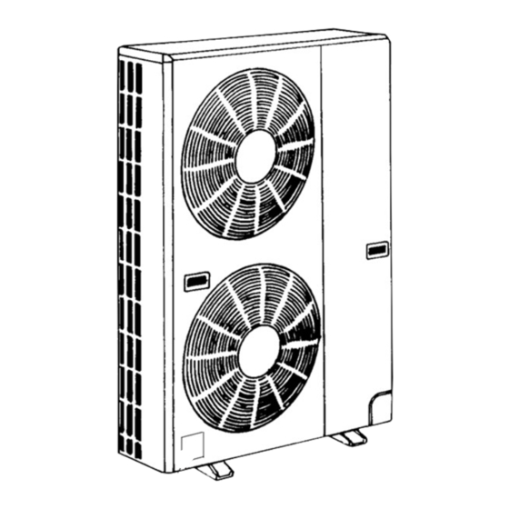
SPLIT-TYPE, HEAT PMUP AIR CONDITIONERS
TECHNICAL & SERVICE MANUAL
R407C
Outdoor unit
[Model name]
PUMY-P125VMA
PUMY-P125YMA
OUTDOOR UNIT
Model name
indication
[Service Ref.]
PUMY-P125VMA
PUMY-P125VMA
PUMY-P125YMA
PUMY-P125YMA
CONTENTS
1. TECHNICAL CHANGE ·····································2
2. SAFETY PRECAUTION····································3
3. OVERVIEW OF UNITS······································5
4. SPECIFICATIONS ·············································8
5. DATA ·······························································10
6. OUTLINES AND DIMENSIONS ······················18
7. WIRING DIAGRAM ·········································19
9. TROUBLESHOOTING ····································34
10. ELECTRICAL WIRING····································78
11. REFRIGERANT PIPING TASKS ·····················81
12. DISASSEMBLY ···············································86
13. PARTS LIST ····················································92
2004
No.OC272
REVISED EDITION-B
Revision :
• PUMY-P125VMA
1
added in REVISED
EDITION-B.
• "9-8.TEST POINT DIA-
1
GRAM " has been
added in REVISED
EDITION-B.
• Please void OC272
1
REVISED EDITION-A.
is
Advertisement
Table of Contents

Related Manuals for Mitsubishi Electric PUMY-P125VMA1


Summary of Contents for Mitsubishi Electric PUMY-P125VMA1
-
Page 1: Table Of Contents
SPLIT-TYPE, HEAT PMUP AIR CONDITIONERS 2004 No.OC272 REVISED EDITION-B TECHNICAL & SERVICE MANUAL R407C Outdoor unit Revision : [Model name] [Service Ref.] • PUMY-P125VMA PUMY-P125VMA added in REVISED EDITION-B. PUMY-P125VMA • “9-8.TEST POINT DIA- PUMY-P125VMA GRAM ” has been added in REVISED PUMY-P125YMA EDITION-B. -
Page 2: Technical Change
TECHNICAL CHANGE OC272 REVISED EDITION-A PUMY-P125YMA PUMY-P125YMA 1. Addition of new function (Auto Change Over) PUMY-P125YMA : Not equipped PUMY-P125YMA : Equipped 2. Difference of operation switching logic for the outdoor output connector (CN3D) PUMY-P125YMA : CN3D 1-2 ······ OPEN : Heating CLOSE : Cooling PUMY-P125YMA : CN3D 1-2 ······... -
Page 3: Safety Precaution
SAFETY PRECAUTION CAUTIONS RELATED TO NEW REFRIGERANT Cautions for units utilizing refrigerant R407C Do not use the existing refrigerant piping. Use liquid refrigerant to charge the system. The old refrigerant and lubricant in the existing piping If gas refrigerant is used to seal the system, the composition contains a large amount of chlorine which may cause the of the refrigerant in the cylinder will change and performance lubricant deterioration of the new unit. - Page 4 [3] Service tools Use the below service tools as exclusive tools for R407C refrigerant. Tool name Specifications Gauge manifold ·Only for R407C. ·Use the existing fitting SPECIFICATIONS. (UNF7/16) ·Use high-tension side pressure of 3.43MPa·G or over. Charge hose ·Only for R407C. ·Use pressure performance of 5.10MPa·G or over.
-
Page 5: Overview Of Units
OVERVIEW OF UNITS 3-1. UNIT CONSTRUCTION PUMY-P125VMA PUMY-P125VMA PUMY-P125YMA PUMY-P125YMA Outdoor unit Capacity Type 20~Type 125 Indoor unit that can be Number of units 1~8 units connected Total system wide capacity 50~130% of outdoor unit capacity CMY-Y62-C-E CMY-Y64-C CMY-Y68 CMY-S65 Branch header Branch header Branch header... - Page 6 3-2. UNIT SPECIFICATIONS (1) Outdoor Unit PUMY-P125VMA PUMY-P125VMA Service Ref. PUMY-P125YMA PUMY-P125YMA Cooling (kW) 14.0 Capacity Heating (kW) 16.0 Motor for compressor (kW) Cooling / Heating capacity indicates the maximum value at operation under the following condition. w. Cooling Indoor : D.B.
- Page 7 3-3. SYSTEM LAYOUT 3-3-1. System layout One outdoor unit using branching connectors can be connected to a maximum of eight indoor units. Examples of a branching method Outdoor unit First branch (branching connector) indoor indoor indoor indoor indoor 3-3-2. Notes on the connection of indoor and outdoor units Note: When the total capacity of indoor units exceeds the capacity of the outdoor unit (more than 100%), the rated power of each indoor unit will be less when they are running simultaneously.
-
Page 8: Specifications
SPECIFICATIONS PUMY-P125VMA Service Ref. Unit Item PUMY-P125VMA Rated Cooling capacity 14.0 Rated power consumption 6.10 Operating current 28.3-27.1-26.0 Operating power factor Starting current Rated Heating capacity 16.0 Rated power consumption 6.03 Operating current 28.0-26.7-25.7 Operating power factor Starting current Rated power supply Single phase 220-230-240V 50Hz External finish (Munsell colour-coded markings) Molten-galvanized steel plate (with polyester coating), ivory white <5Y 8/1>... - Page 9 Service Ref. PUMY-P125YMA Unit Item PUMY-P125YMA Rated Cooling capacity 14.0 Rated power consumption 5.95 Operating current 9.6-9.1-8.8 Operating power factor Starting current Rated Heating capacity 16.0 Rated power consumption 5.58 Operating current 9.2-8.8-8.5 Operating power factor Starting current Rated power supply 3 phase 380-400-415V 50Hz External finish (Munsell colour-coded markings) Molten-galvanized steel plate (with polyester coating), ivory white <5Y 8/1>...
-
Page 10: Data
DATA 5-1. COOLING AND HEATING CAPACITY AND CHARACTERISTICS 5-1-1. Method for obtaining system cooling and heating capacity: To obtain the system cooling and heating capacity and the electrical characteristics of the outdoor unit, first add up the ratings of all the indoor units connected to the outdoor unit (see table below), and then use this total to find the standard capacity with the help of the tables on page 11 to 14. - Page 11 5-2. STANDARD CAPACITY DIAGRAM 5-2-1. PUMY-P125VMA, PUMY-P125VMA STANDARD CAPACITY DIAGRAM Before calculating the sum of total capacity of indoor units, please convert 240V, 50Hz the valve into the kW model capacity following the formula on page 10. Power consumption (kW) Current (A) Total capacity of Capacity (kW)
- Page 12 5-2-2. PUMY-P125VMA, PUMY-P125VMA STANDARD CAPACITY DIAGRAM Before calculating the sum of total capacity of indoor units, please convert the valve into the kW model capacity following the formula on page 10. 240V, 50Hzw Power consumption (kW) Current (A) Capacity (kW) Total capacity of Cooling Cooling...
- Page 13 5-2-3. PUMY-P125YMA, PUMY-P125YMA STANDARD CAPACITY DIAGRAM Before calculating the sum of total capacity of indoor units, please convert the valve into the kW model capacity following the formula on page 10. 415V, 50Hz Power consumption (kW) Current (A) Total capacity of Capacity (kW) indoor units Cooling...
- Page 14 5-2-4. PUMY-P125YMA, PUMY-P125YMA STANDARD CAPACITY DIAGRAM Before calculating the sum of total capacity of indoor units, please convert the valve into the kW model capacity following the formula on page 10. 415V, 50Hzw Power consumption (kW) Current (A) Capacity (kW) Total capacity of Cooling Cooling...
- Page 15 5-3. CORRECTING COOLING AND HEATING CAPACITY 5-3-1. Correcting Changes in Air Conditions (1)The performance curve charts (Figure 1, 2) show the rated capacity (total capacity) under the stated conditions when standard length for piping (5m) is used. The rated power is derived from the capacity ratio and power ratio obtained for the indoor and outdoor intake temperatures at time 1.
- Page 16 5-3-2. Correcting Capacity for Changes in the Length of Refrigerant Piping (1) During cooling, to obtain the ratio (and the equivalent piping length) of the outdoor units rated capacity and the total in-use indoor capacity, first find the capacity ratio corresponding to the standard piping length (5m) from Figures 3 at first, and then multiply by the cooling capacity from Figure 1 to obtain the actual capacity.
- Page 17 PUMY-P125VMA NOTCH SPL(dB) LINE PUMY-P125VMA PUMY-P125YMA PUMY-P125YMA NC-70 NC-60 NC-50 NC-40 NC-30 APPROXIMATE THRESHOLD OF HEARING FOR NC-20 CONTINUOUS NOISE 500 1000 2000 4000 8000 BAND CENTER FREQUENCIES, Hz MICROPHONE...
-
Page 18: Outlines And Dimensions
OUTLINES AND DIMENSIONS • OUTDOOR UNITS unit : mm PUMY-P125VMA PUMY-P125VMA PUMY-P125YMA PUMY-P125YMA... -
Page 19: Wiring Diagram
WIRING DIAGRAM PUMY-P125VMA PUMY-P125VMA SYMBOL NAME SYMBOL NAME SYMBOL NAME SYMBOL NAME Terminal Block(Power Supply) Magnetic Contactor N.F. Noise Filter Circuit Board CNS1 Connector(Multi system) Terminal Block(Transmission) 21S4 4-Way Valve Connection Lead(L-Phase) CNS2 LI/LO Connector(Centralized Control) Solenoide Valve(Hot Gas Bypass) Connection Lead(N-Phase) Connector Terminal Block(Centralized Control) - Page 20 PUMY-P125YMA SYMBOL SYMBOL NAME NAME SYMBOL NAME SYMBOL NAME THERMISTOR C1,C2 FAN MOTOR CAPACITOR SOLENOID VALVE <HOT GAS BYPASS> ACCT CONNECTOR <CURRENT DETECTION> <LOW PRESSURE SATURATED DIODE MODULE SWITCH <DISPLAY SELECTION> CB1,CB2 SMOOTHING CAPACITOR TEMPERATURE DETECTION> THERMISTOR REACTOR SWITCH <FUNCTION SELECTION> CONNECTOR <POWER SUPPLY>...
- Page 21 PUMY-P125YMA SYMBOL NAME SYMBOL NAME SYMBOL NAME SYMBOL NAME ACCT CONNECTOR <CURRENT DETECTION> C1,C2 FAN MOTOR CAPACITOR SOLENOID VALVE <HOT GAS BYPASS> THERMISTOR <LOW PRESSURE SATURATED TEMP. DETECTION> CB1,CB2 SMOOTHING CAPACITOR DIODE MODULE SWITCH <DISPLAY SELECTION> CONNECTOR <POWER SUPPLY> REACTOR SWITCH <FUNCTION SELECTION>...
-
Page 22: Necessary Conditions For System Construction
NECESSARY CONDITIONS FOR SYSTEM CONSTRUCTION 8-1. TRANSMISSION SYSTEM SETUP... - Page 23 8-2. REFRIGERANT SYSTEM DIAGRAM PUMY-P125VMA PUMY-P125VMA (Refrigerant flow) Cooling PUMY-P125YMA Heating Thermistor TH6 (outdoor air PUMY-P125YMA High-pressure sensor temperature detection) discharge pressure detection (63HS) Service port 4-way valve Strainer Check valve separator (High pressure) Flare Strainer (#100) Check valve Thermistor (low pressure) (discharge Strainer...
- Page 24 8-3. SYSTEM CONTROL 8-3-1. Operating a Single Refrigerant System When operating either alone or as part of a group, a M-NET remote controller (NR) may be used to control a single refrigerant system that does not overlap with any other system. <Example of system arrangement>...
- Page 25 8-3-2. System Controller (SC) to Perform Centralized Control <Example of System Arrangement> The following diagram shows the use of system controller (SC) to control a system that includes the multiple outdoor unit. Indoor • outdoor transmission wire (Shielded wire) <Room A> <Room B>...
- Page 26 8-3-3. Example for the System • Example for wiring control cables, wiring method and address setting, permissible lengths, and the prohibited items are listed in the standard system with detailed explanation. The explanation for the system in this section : Use one single outdoor unit and multiple outdoor units for M-NET remote control system.
- Page 27 • Name, Symbol and the Maximum Remote controller Units for Connection Symbol Name Maximum units for connection Outdoor unit Indoor unit One OC unit can be connect to 1-8 IC units M-NET remote Maximum two NR for one indoor unit, Maximum 16 NR for one OC controller Permissible Lengths Prohibited items...
- Page 28 B. Example of a group operation system with two or more outdoor units and a M-NET remote controller. (Shielding wires and address settings are necessary.) Between terminal blocks Group 1 Group 3 Group 5 CN40 (051) (001) (004) (005) (006) TB15 TB15 TB15...
- Page 29 • Name, Symbol, and the Maximum Units for Connection • Max length via outdoor units : L [ 500 meters (1.25mm [ 200 meters (1.25mm • Max transmission cable length : L [ 10 meters (0.5 to 0.75mm • Remote controller cable length : R If the length exceeds 10 meters, use a 1.25 mm shielded wire.
- Page 30 C. Example of a MA remote controller system (address setting is not necessary.) NOTE : In the case of same group operation, need to set the address that is only main indoor unit. Example of wiring control cables Wiring Method and Address Setting 1.
- Page 31 Permissible Lengths Prohibited items The MA remote controller and the Longest transmission cable length [ 200m (1.25 mm M-NET remote controller cannot be used together with the indoor unit MA remote controller cable length [ 200m (0.3 ~ 1.25 mm the of the same group.
- Page 32 D. Example of a group operation with two or more outdoor units and a MA remote controller. (Shielding wires and address settings are necessary.) Between terminal blocks Group 1 Group 5 Group 3 CN40 CN41 (051) (001) (004) (005) (006) TB5 TB15 TB5 TB15 TB5 TB15...
- Page 33 • Name, Symbol, and the Maximum Units for Connection • Max length via outdoor units : L [ 500 meters (1.25mm [ 200 meters (1.25mm • Max transmission cable length : L [ 10 meters (0.5 to 0.75mm • Remote controller cable length : R If the length exceeds 10 meters, use a 1.25 mm shielded wire.
-
Page 34: Troubleshooting
TROUBLESHOOTING 9-1. CHECK POINTS FOR TEST RUN 9-1-1. Procedures of test run (1) Before test run, make sure that following work is completed. • Installation related : Make sure that the panel of cassette type and electrical wiring is done. Otherwise electrical functions like auto vane will not operate normally. - Page 35 9-1-2. Special Function Operation and Settings (for M-NET Remote Controller) • It is necessary to perform “group settings” and “paired settings” at making group settings of different refrigerant systems (multiple outdoor unit). (A) Group settings: Enter the indoor unit controlled by the remote controller, check the content of entries, and clear entries, etc.
- Page 36 (2) Address check: Refer to section (1) regarding address entry. a) In making group settings: • Turn off the remote controller: Press the remote controller's ON/OFF button to stop operation (the indicator light will go off). • Locate the indoor unit address display mode: Press the FILTER and k buttons on the remote controller simultaneously and hold for two seconds.
- Page 37 9-1-3. Countermeasures for Error During Test Run • If a problems occurs during test run, a code number will appear in the temperature display area on the remote controller (or LD1 on the outdoor unit), and the air conditioning system will automatically cease operating. Determine the nature of the abnormality and apply corrective measures.
- Page 38 Display Meaning and detecting method Check points Causes 1102 Discharge temperature abnormality 1) Gas leakage, Gas shortage When the discharge temperature thermistor Check the refrigerant amount. (TH1) detects 125 or more (1st detection), Check the indoor/outdoor unit operating 2) Overloaded operation the compressor stops and restarts operation condition and status.
- Page 39 Display Meaning and detecting method Check points Causes 1302 5) Indoor fan motor lock Check the indoor fan motor. When the sensor detects 2.94MPa or more again (2nd detection) within 30 minutes 6) Indoor fan motor failure Check the indoor fan motor. since the compressor has stopped, the 7) 4-way valve performance failure Change COOL/HEAT operation mode...
- Page 40 Display Meaning and detecting method Check points Causes 1500 2. The compressor has operated 4) Discharge super heat detection error consecutively 20 minutes or more, since High-pressure pressure sensor Check the high-pressure pressure the indoor unit operation capacity had failure sensor.
- Page 41 Display Meaning and detecting method Check points Causes Vacuum operation protection 1505 1) Ball valve performance failure (not Check the ball valve is full opened. When the suction pressure saturation full opened.) temperature thermistor (TH2) detects -13; or less and ''[indoor temperature-liquid pipe 2) Light-loaded operation (When outer Check the indoor/outdoor unit temperature][ 8deg'' for 3minutes...
- Page 42 Display Meaning and detecting method Check points Causes 2502 Drain pump abnormality (Note) Address/Attribute displayed on the remote controller shows the indoor unit which is cause of trouble. <Detected timing> Always detecting regardless of the indoor unit status. <Abnormality clear> Abnormality is cleared by either of two of the following;...
- Page 43 Display Meaning and detecting method Check points Causes 4116 Fan rotational frequency abnormality 1) Fan rotational frequency detecting Check whether the connector (CN33) (Detected only PKFY-P·VAM-A) connector (CN33) disconnection in the in the indoor controller board is indoor controller board. disconnected or not.
- Page 44 Display Meaning and detecting method Check points Causes 4220 PUMY-P125YMA PUMY-P125YMA Measure the terminal voltage, and 1) Power supply terminal voltage is low. Shortage abnormality of inverter bus-bar check whether the voltage decreases voltage or not. When direct current bus-bar voltage 2) Power supply L2,L3-phase is Check the power supply is opened.
- Page 45 Display Meaning and detecting method Check points Causes PUMY-P125YMA IPM abnormality 4250 The interruption happens by accident. PUMY-P125YMA Over current limited Since the interception only once 1) Single interruption by external noise. returns automatically after restarting in (When the compressor is interrupted by 3minutes, the possibility to stop over current at its start-up.) abnormally is very few.
- Page 46 From the preceding page. Display Meaning and detecting method Check points Causes When not applying from 4 to 7, it 4250 applies to 9) and 10). Check the compressor. In case of 10), recheck the compressor again after 12 hours with former power supply.
- Page 47 Display Meaning and detecting method Check points Causes 5102 Liquid pipe temperature thermistor (TH22) abnormality When the thermistor detects short/open 1) Connector (CN21) contact failure Check whether the connector during the operation, the operation stops (CN21) in the indoor controller board and the operation changes to protect mode is connected or not.
- Page 48 Display Meaning and detecting method Check points Causes 5103 Gas pipe temperature thermistor (TH23) abnormality 1) Connector (CN29) contact failure Check whether the connector (CN29) When the thermistor detects short/open in the indoor controller board is after 3minutes-continuous thermo ON connected or not.
- Page 49 Display Meaning and detecting method Check points Causes 5106 Outdoor temperature thermistor (TH6) abnormality 1) Connector (TH6) contact failure Check whether the connector (TH6) in the multi controller board is When controller detects short/open in connected or not. thermistor during the operation, the outdoor unit stops once and restarts operation in 3minutes.
- Page 50 Display Meaning and detecting method Check points Causes 5201 Pressure sensor (63HS) abnormality When detected pressure in high-pressure 1) High-pressure pressure sensor Check the high-pressure pressure pressure sensor is 1MPa or less during the failure sensor. operation, the compressor stops and restarts operation in 3minutes.
- Page 51 Display Meaning and detecting method Check points Causes 6603 Transmission bus busy error Over error by collision 1) The transmission processor cannot Check whether the transmission line be transmitted since a short cycle of the indoor unit, fresh master, Abnormality when the state, which cannot voltage of the noise etc.
- Page 52 Display Meaning and detecting method Check points Causes No ACK (Acknowledgement) 6607 Factor that not related to origin Abnormality which controller of the 1) Since the address switch was Turn off power supply of outdoor unit, sending side detects when there is no changed with the current passed, the indoor unit fresh master and lossnay answer (ACK) from other side though data...
- Page 53 Display Meaning and detecting method Check points Causes 3) When the cause of displayed address 1) When operating with multi refrigerant 6607 and attribute is on the remote controller system indoor units, the indoor units side transmits the signal to the remote controller after the other refrigerant (The indoor unit detects when there is no system outdoor unit is turned off or...
- Page 54 Display Meaning and detecting method Check points Causes 6607 2) When synchronized operating with other refrigerant system lossnay, the indoor units transmits the signal to the lossnay after the lossnay and same refrigerant system outdoor unit is turned off or turned on again in 2minutes, and detects abnormality 3) Contact failure of lossnay or indoor unit transmission line...
- Page 55 Display Meaning and detecting method Check points Causes 6810 UR communication abnormality (UR: Unit Remote controller) Communications between the unit remote 1) Contact failure of the unit remote Check whether the transmission line controller and indoor unit is not normal. controller transmission line in the unit of the indoor unit or unit remote remote controller or indoor unit.
- Page 56 Display Meaning and detecting method Check points Causes When connected total models of the 1) Connecting total models of the Check the total models of connected 7100 indoor units exceed the specified level indoor unit exceed the specified level. indoor unit. (130% of the outdoor unit models), error code <7100>...
- Page 57 Display Meaning and detecting method Check points Causes 7105 Address setting error Address setting of the outdoor unit is Addresses miss setting of the outdoor Check the address setting of the wrong. unit. outdoor unit. The address should be set in 000 or 51-100. The outdoor unit is not set in 000 or in the range of 51-100.
- Page 58 From the preceding page. Potential problems other than those diagnosed for the remote controller. a) Single transmission not possible if error display 2 (“6832 or 6833”) flashes. There is “noise” on the transmission line, or damage of other remote controller for the indoor units can be considered.
- Page 59 (2) For MA remote controller systems Symptom or inspection code Cause Inspection method and solution Though the content of operation is • The power supply of the indoor unit is not on. • Check the part where the • Wiring between indoor units in same group is not finished. abnormality occurs.
- Page 60 9-5. INTERNAL SWITCH FUNCTION TABLE 9-5-1. Outdoor unit internal switch function table (PUMY-P125VMA PUMY-P125VMA Operation in Each Switch Setting Switch Step Function Remarks When to Set <Factory Settings> SW U1 1st digit Before turning W The address automatically becomes the power on "100"...
- Page 61 9-5-2. Outdoor unit internal switch function table (PUMY-P125YMA PUMY-P125YMA Operation in Each Switch Setting Switch Step Function Remarks When to Set <Factory Settings> SW U1 1st digit Before turning SW U2 the power on 2nd digit SWU3 SWU2 SWU1 SWU3 SWU2 SWU1 SW U3...
- Page 62 9-6. OUTDOOR UNIT INPUT/OUTPUT CONNECTOR State (CN51) Distant control External output board adapter Relay circuit Outdoor unit control board CN51 Preparations Maximum cable in the field length is 10m : Error display lamp : Compressor operation lamp X, Y : Relay (Coil standard of 0.9W or less for DC 12V) External output Comp ON/OFF (CN3S) adapter...
- Page 63 9-7. HOW TO CHECK THE PARTS PUMY-P125VMA PUMY-P125VMA PUMY-P125YMA PUMY-P125YMA Parts name Check points •Thermistor (TH1) Disconnect the connector then measure the resistance using a tester. (Surrounding temperature 10:~30:) <Discharge temperature detection> Normal Abnormal •Thermistor (TH2) <Low pressure saturated 160k"~410k" temperature detection>...
- Page 64 From the preceding page. PUMY-P125VMA PUMY-P125VMA Medium temperature thermistor •Thermistor (THHS A/B) <Radiator panel> Thermistor R50 = 17k' ± 2% B constant = 4150K ± 3% =17exp{4150( 273+t – 323 )} 180k' 50k' 17k' Temperature (:) PUMY-P125YMA, PUMY-P125YMA Medium temperature thermistor •Thermistor (THHS) <IPM radiator panel temperature thermistor detection>...
- Page 65 <HIGH PRESSURE SENSOR> Vout (V) MULTI CONTROLLER BOARD 5V DC Vout MICRO COMPUTER 63HS 3-1 : 5V (DC) 2-1 : Vout (DC) PRESSURE (MPa) Expansion valve (LEV(A), SLEV: Outdoor unit) 1 1 Notes on expansion valve action • LEV(A), SLEV to stepping motor ON/OFF after outdoor controller board has received pulse signal. •...
- Page 66 From the preceding page. 3 Troubleshooting <Output pulse signal and valve action> Valve closing:1 2 3 4 1 Output Valve opening:4 3 2 1 4 Output(phase) The address of the pulse output is shifted using the procedures mentioned earlier. w1. All output phase will turn OFF when the LEV(A), SLEV stops operating.
- Page 67 9-8. TEST POINT DIAGRAM Connect to the outdoor power supply board (CN1) 9-8-1. Outdoor multi controller board 1:52C relay output signal 2:4-way valve output signal PUMY-P125YMA 3:Bypass valve output signal AC,CT PUMY-P125YMA 4:OPEN Detection of 5:OPEN cureent 6:Fan draive signal SLEV Connect to the outdoor power supply board (CN2) Expansion...
- Page 68 9-8-2. Outdoor power supply board PUMY-P125YMA PUMY-P125YMA U, V, W Connect to the compressor (MC) Voltage among Connect to Connect to phases: 5V-400V AC CB1(+) CB2 (+) Connect to 52C Connect to the outdoor resistor board (CNR) <Inverter sigunal> Connect to Connect CB2 (–) to the...
- Page 69 9-8-3. Outdoor resistor board PUMY-P125YMA PUMY-P125YMA Connect to the outdoor 220-240V AC power supply board (CNR) Connect to the noise filter (CNA)
- Page 70 9-8-4. Outdoor multi circuit board CNDC PUMY-P125VMA 300-380V DC Connect to the outdoor PUMY-P125VMA MF1, MF2 power circuit board (CNDC) Connect to fan motor – Signal wires Connect to the outdoor power circuit board (CN2) 52C Relay 21S4 Four-way valve Bypass valve CNAC CN51...
- Page 71 Brief Check of POWER MODULE W Usually, they are in a state of being short-circuited if they are broken. 9-8-5. Outdoor power circuit board Measure the resistance in the following points (connectors, etc.). PUMY-P125VMA If they are short-circuited, it means that they are broken. PUMY-P125VMA 1.
- Page 72 LO, NO 9-8-6. Outdoor noise filter circuit board Voltage of 220-240V AC is output PUMY-P125VMA (Connect to the outdoor power PUMY-P125VMA circuit board (SC-R, SC-S)) CNAC1, CNAC2 220-240V AC (Connect to the outdoor multi circuit board (CNAC)) Primary current (Connect to the outdoor power circuit board (CN5))
- Page 73 SW:setting 0..OFF 9-9. OUTDOOR UNIT FUNCTIONS 1..ON...
-
Page 78: Electrical Wiring
ELECTRICAL WIRING This chapter provides an introduction to electrical wiring for the MULTI-S series, together with notes concerning power wiring, wiring for control (transmission wires and remote controller wires), and the frequency converter. 10-1. OVERVIEW OF POWER WIRING (1) Please refer to your electric power company about the indoor wiring specifications for the power wire diameter and capacity of protective devices (switches and leakage of breakers). - Page 79 10-3. DESIGN FOR CONTROL WIRING Please note that the types and numbers of control wires needed by the CITY MULTI-S series will depend on the remote controllers and whether they are linked with the system. 10-3-1. Selection number of control wires M-NET remote controller Remote controller used in system control operations.
- Page 80 10-4. SYSTEM SWITCH SETTING In order to identify the destinations of signals to the outdoor units, indoor units, and remote controller of the MULTI-S series, each microprocessor must be assigned an identification number (address). The addresses of outdoor units, indoor units, and remote controller must be set using their settings switches.
-
Page 81: Refrigerant Piping Tasks
REFRIGERANT PIPING TASKS 11-1. REFRIGERANT PIPING SYSTEM Line-Branch Method Connection Examples (Connecting to Four Indoor Units) Outdoor Unit First Branch Indoor unit Total Piping Length A+B+C+a+b+c+d is 100 meters or less Permissible Farthest Piping Length A+B+C+d is 70 meters or less Length Farthest Piping Length After First Branch B+C+d is 30meters or less... - Page 82 Header-Branch Method Connection Examples (Connecting to Four Indoor Units) Outdoor Unit First Branch Indoor unit Total Piping Length A+a+b+c+d is 100 meters or less Permissible Farthest Piping Length A+d is 70 meters or less Length Farthest Piping Length After First Branch d is 30 meters or less High/Low Difference in Indoor/Outdoor Section 30 meters or less (If the outdoor unit is lower, 20 meters or less)
- Page 83 Note: The total of downstream unit models in the table is the total of models as seen from point A in the figure above. Note: Pipe re-branching after the header branching is not possible. Method of Combined Branching of Lines and Headers Connection Examples (Connecting to Five Indoor Units)
- Page 84 Multi-distribution piping on outdoor unit Connection Examples (Connecting up to Five Indoor Units) *If multi-distribution piping on outdoor unit is Outdoor Unit done, a maximum of 5 indoor units can be First Branch connected. Cannot redistribute the piping. Indoor unit Permissible Total Piping Length a+b+c+d+e is 100 meters or less...
- Page 85 11-2. PRECAUTIONS AGAINST REFRIGERANT LEAKAGE 11-2-1. Introduction (2) Calculate room volumes (in K) and find the room with the smallest volume R-22 refrigerant of this air conditioner is non-toxic and non- flammable but leaking of large amount from an indoor unit The part with represents the room with the smallest into the room where the unit is installed may be deleterious.
-
Page 86: Disassembly
DISASSEMBLY Service Ref. : PUMY-P125VMA 1. Please pay attention to safety when assembling or disassembling heavy items. 2. The refrigerant system must be vacuum-pumped before performing piping maintenance. PUMY-P125VMA PUMY-P125YMA PUMY-P125YMA OPERATING PROCEDURE PHOTOS Photo 1 Top panel 1. Side and top panel disassembly procedures: installation screws Top panel (1) Remove the side panel screws (3 pcs : 5o10 screws) - Page 87 OPERATING PROCEDURE PHOTOS Photo 4 3. Thermistor (TH6: outdoor air temperature sensor Thermistor detection) disassembly procedures: (air temperature (1) Remove the side panel (See photo 1) Thermistor holder screw detection) (2) Remove the top panel (See photo 1) (3) Remove the thermistor holder fixing screw (1 pc : 4o10), and remove the thermistor holder.
- Page 88 OPERATING PROCEDURE PHOTOS Photo 6 5. Electrical parts box disassembly procedures: PUMY-P125YMA [PUMY-P125YMA PUMY-P125YMA PUMY-P125YMA Remove the side panel (See photo 1) Remove the top panel (See photo 1) Disconnect the following wires from the Board plate Power supply board multi controller board.
- Page 89 OPERATING PROCEDURE PHOTOS Photo 8 7. Thermistor disassembly procedures: separator (1) Remove the side panel (See photo 1) Piping cover (2) Remove the top panel (See photo 1) (3) Remove the electrical parts box (See photo 5 or 6) Thermistor (4) Recover gas from the refrigerant circuit.
- Page 90 OPERATING PROCEDURE PHOTOS Photo 11 Pipe of heat exchanger inlet (T connector) 10. Four-way valve disassembly procedures: (1) Remove the side panel (See photo 1). (2) Remove the top panel (See photo 1). (3) Remove the electrical parts box (See photo 5 or 6). Accumulator inlet (4) Recover gas from the refrigerant circuit.
- Page 91 OPERATING PROCEDURE PHOTOS Photo 14 13. High pressure sensor (63HS)disassembly procedures: (1) Remove the side panel (See photo 1). fixing screw (2) Remove the high pressure sensor wire. (3) Recover gas from the refrigerant circuit. (4) Remove the welded portion of high pressure sensor. (5) Remove the mounting screw fastening the high pressure sensor mounting plate (1 pc : 4o10).
-
Page 92: Parts List
PARTS LIST W The illustration below is of PUMY-P125VMA ELECTRICAL PARTS PUMY-P125VMA PUMY-P125VMA ty/set Price Wiring Recom- Remarks Part No. Part Name Specification Diagram mended PUMY-P (Drawing No.) Symbol Unit Amount 125VMA125VMA R01 580 255 FAN MOTOR CAPACITOR 3.5µF 440VAC C1,2 T7W E19 315 MULTI CIRCUIT BOARD... - Page 93 ELECTRICAL PARTS PUMY-P125YMA PUMY-P125YMA 13 VARISTOR ty/set Price Wiring Recom- Remarks PUMY-P125 Part No. Part Name Specification Diagram mended (Drawing No.) Symbol Unit Amount YMA YMA R01 580 255 FAN MOTOR CAPACITOR 3.5µF 440VAC C1,2 T7W E02 239 FUSE 2A 250V FUSE2 T7W 520 239 FUSE...
- Page 94 FUNCTIONAL PARTS PUMY-P125VMA PUMY-P125VMA PUMY-P125YMA PUMY-P125YMA...
- Page 95 Part number that is circled is not shown in the figure. ty/set Price Wiring Recom- PUMY-P125 Remarks Part No. Part Name Specification Diagram mended (Drawing No.) Symbol Unit Amount YMA YMA PROPELLER R01 KL5 115 R01 30L 097 R01 35A 202 THERMISTOR (DISCHARGE TEMPERATURE DETECTION) R01 E00 268 HIGH PRESSURE SENSOR...
- Page 96 STRUCTURAL PARTS PUMY-P125VMA PUMY-P125VMA PUMY-P125YMA PUMY-P125YMA 13 SCREW ty/set Price PUMY-P125 Remarks Wiring Recom- Part No. Part Name Specification Diagram mended (Drawing No.) Symbol Unit Amount YMA YMA R01 KN4 675 FAN GUARD R01 38A 668 FRONT PANEL R01 KL5 655 PANEL HANDLE R01 38A 686 BASE...
- Page 98 HEAD OFFICE : MITSUBISHI DENKI BLDG., 2-2-3, MARUNOUCHI, CHIYODA-KU, TOKYO100-8310, JAPAN cCopyright 2001 MITSUBISHI ELECTRIC ENGINEERING CO., LTD. Distributed in Aug. 2004 No.OC272 REVISED EDITON-B PDF 9 Distributed in Sep. 2003 No.OC272 REVISED EDITON-A PDF 11 Distributed in Dec. 2001 No.OC272 PDF 300 New publication, effective Aug.
Need help?
Do you have a question about the PUMY-P125VMA1 and is the answer not in the manual?
Questions and answers