Tektronix Keithley SourceMeter 2461 User Manual
1 kw pulse mode interactive
Hide thumbs
Also See for Keithley SourceMeter 2461:
- User manual (105 pages) ,
- Quick start manual (24 pages) ,
- Calibration and adjustment manual (59 pages)
Table of Contents
Troubleshooting

Subscribe to Our Youtube Channel
Related Manuals for Tektronix Keithley SourceMeter 2461


Summary of Contents for Tektronix Keithley SourceMeter 2461
- Page 1 www.keithley.com Model 2461 1 kW Pulse Mode Interactive SourceMeter® Instrument User’s Manual 2461-900-01 Rev. A / November 2015 *P246190001A* 2461-900-01A A Greater M easure of Confidence A T ektr onix Company...
- Page 2 Model 2461 ® Interactive SourceMeter Instrument User's Manual © 2015, Keithley Instruments Cleveland, Ohio, U.S.A. All rights reserved. Any unauthorized reproduction, photocopy, or use of the information herein, in whole or in part, without the prior written approval of Keithley Instruments is strictly prohibited. ®...
- Page 3 Safety precautions The following safety precautions should be observed before using this product and any associated instrumentation. Although some instruments and accessories would normally be used with nonhazardous voltages, there are situations where hazardous conditions may be present. This product is intended for use by qualified personnel who recognize shock hazards and are familiar with the safety precautions required to avoid possible injury.
- Page 4 For safety, instruments and accessories must be used in accordance with the operating instructions. If the instruments or accessories are used in a manner not specified in the operating instructions, the protection provided by the equipment may be impaired. Do not exceed the maximum signal levels of the instruments and accessories, as defined in the specifications and operating information, and as shown on the instrument or test fixture panels, or switching card.
-
Page 5: Table Of Contents
Table of Contents Introduction ....................... 1-1 Welcome ..........................1-1 Introduction to this manual ....................1-1 Extended warranty ....................... 1-1 Contact information ......................1-2 CD-ROM contents ........................ 1-2 Organization of manual sections ..................1-2 Applications .......................... 1-3 Using the front-panel interface ................2-1 Front panel overview ...................... - Page 6 Table of Contents Model 2461 Interactive SourceMeter® Instrument User's Manual Making basic front-panel measurements ..............4-1 Introduction .......................... 4-1 Equipment required for this application................4-2 Device connections ......................4-2 Make front-panel measurements ..................4-2 How to make front-panel measurements .................. 4-3 Measuring low-resistance devices ................
- Page 7 Model 2461 Interactive SourceMeter® Instrument User's Manual Table of Contents Set up remote communications ................... 8-2 Device connections ......................8-2 Solar panel characterization ....................8-4 Set up the solar panel I-V sweep from the front panel .............. 8-4 Set up the solar panel I-V sweep using SCPI commands ............8-6 Set up the solar panel I-V sweep using TSP commands ............
- Page 8 Table of Contents Model 2461 Interactive SourceMeter® Instrument User's Manual What are the Quick Setup options? ................... 11-5 Next steps ....................... 12-1 Additional Model 2461 information ..................12-1...
-
Page 9: Introduction
Section 1 Introduction In this section: Welcome .................. 1-1 Introduction to this manual ............1-1 Extended warranty ..............1-1 Contact information ..............1-2 CD-ROM contents ..............1-2 Organization of manual sections ..........1-2 Applications ................1-3 Welcome Thank you for choosing a Keithley Instruments product. The Model 2461 1 kW Pulse Mode Interactive ®... -
Page 10: Contact Information
Section 1: Introduction Model 2461 Interactive SourceMeter® Instrument User's Manual Contact information If you have any questions after you review the information in this documentation, please contact your local Keithley Instruments office, sales partner, or distributor. You can also call Keithley Instruments corporate headquarters (toll-free inside the U.S. -
Page 11: Applications
Model 2461 Interactive SourceMeter® Instrument User's Manual Section 1: Introduction Troubleshooting FAQs (on page 11-1): Provides answers to frequently asked questions to help you troubleshoot common problems encountered with the Model 2461. Next steps (on page 12-1): Provides information about additional resources that can help you use the Model 2461. - Page 12 Section 2 Using the front-panel interface In this section: Front panel overview ..............2-1 Power the instrument on or off ..........2-3 Turn the Model 2461 output on or off ........2-4 Touchscreen display..............2-5 Store measurements on a USB flash drive ......2-10 Saving screen captures to a USB flash drive ......
-
Page 13: Using The Front-Panel Interface
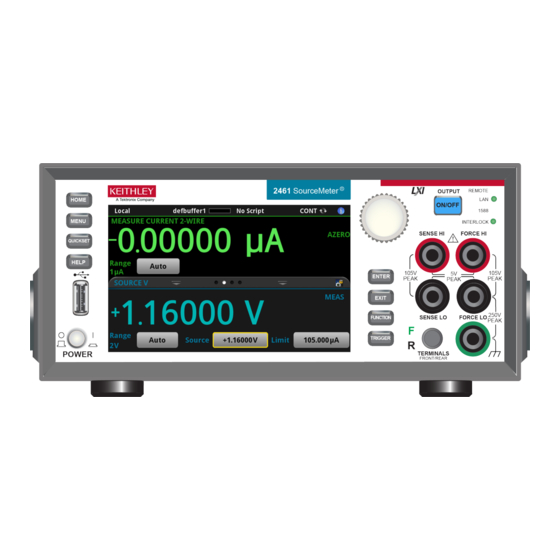
Section 2: Using the front-panel interface Model 2461 Interactive SourceMeter® Instrument User's Manual POWER switch Turns the instrument on or off. To turn the instrument on, press the power switch so that it is in the on position (|). To turn it off, press the power switch so that it is in the off position (O). -
Page 14: Power The Instrument On Or Off
Model 2461 Interactive SourceMeter® Instrument User's Manual Section 2: Using the front-panel interface REMOTE LED Illuminates when the instrument is controlled through a remote indicator interface. LAN LED indicator Illuminates when the instrument is connected to a local area network (LAN). -
Page 15: Turn The Model 2461 Output On Or Off
Section 2: Using the front-panel interface Model 2461 Interactive SourceMeter® Instrument User's Manual Do not replace detachable mains supply cords with inadequately rated cords. Failure to use properly rated cords may result in personal injury or death due to electric shock. To connect the power cord: 1. -
Page 16: Touchscreen Display
Model 2461 Interactive SourceMeter® Instrument User's Manual Section 2: Using the front-panel interface When the source of the instrument is turned off, it may not completely isolate the instrument from the external circuit. You can use the Output Off setting to place the Model 2461 in a known, noninteractive state during idle periods, such as when you are changing the device under test. -
Page 17: Scroll Bars
Section 2: Using the front-panel interface Model 2461 Interactive SourceMeter® Instrument User's Manual Scroll bars Some of the interactive screens have additional options that are only visible when you scroll down the screen. A scroll indicator on the right side of the touchscreen identifies these screens. Swipe the screen up or down to view the additional options. - Page 18 Model 2461 Interactive SourceMeter® Instrument User's Manual Section 2: Using the front-panel interface Screen element Description Minimize indicator You can swipe down to minimize the swipe screens. Swipe screen indicator Each circle represents one swipe screen. As you swipe right or left, a different circle changes color, indicating where you are in the screen sequence.
- Page 19 Section 2: Using the front-panel interface Model 2461 Interactive SourceMeter® Instrument User's Manual SETTINGS swipe screen The SETTINGS swipe screen gives you front-panel access to some instrument settings. It shows you the present settings and allows you to change, enable, or disable them quickly. Figure 6: SETTINGS swipe screen To disable or enable a setting, select the box next to the setting so that it shows an X (disabled) or a check mark (enabled).
-
Page 20: Menu Overview
Model 2461 Interactive SourceMeter® Instrument User's Manual Section 2: Using the front-panel interface GRAPH swipe screen The GRAPH swipe screen shows a graphical representation of the readings in the presently selected reading buffer. Figure 9: GRAPH swipe screen To view the graph in the full screen and to access graph settings, select the graph icon on the right side of the swipe screen header. -
Page 21: Store Measurements On A Usb Flash Drive
Section 2: Using the front-panel interface Model 2461 Interactive SourceMeter® Instrument User's Manual Store measurements on a USB flash drive If there is measurement data in the buffer, you can copy it from the Model 2461 to a USB flash drive. The information is saved in the .csv file format. -
Page 22: Using A Remote Interface
Section 3 Using a remote interface In this section: Remote communications interfaces.......... 3-1 Supported remote interfaces ............ 3-1 GPIB communications .............. 3-2 LAN communications..............3-4 USB communications ............... 3-6 Using the web interface ............3-10 Determining the command set you will use ......3-12 Remote communications interfaces You can choose from one of several communication interfaces to send commands to and receive responses from the Model 2461. -
Page 23: Gpib Communications
Section 3: Using a remote interface Model 2461 Interactive SourceMeter® Instrument User's Manual GPIB communications The Model 2461 GPIB interface is IEEE Std 488.1 compliant and supports IEEE Std 488.2 common commands and status model topology. You can have up to 15 devices connected to a GPIB interface, including the controller. The maximum cable length is the lesser of either: ... -
Page 24: Set The Gpib Address
Model 2461 Interactive SourceMeter® Instrument User's Manual Section 3: Using a remote interface To allow many parallel connections to one instrument, stack the connectors. Each connector has two screws to ensure that connections remain secure. The figure below shows a typical connection diagram for a test system with multiple instruments. -
Page 25: Lan Communications
Section 3: Using a remote interface Model 2461 Interactive SourceMeter® Instrument User's Manual To set the GPIB address from the front panel: 1. Press the MENU key. 2. Under System, select Communication. The SYSTEM COMMUNICATIONS window opens. 3. Select the GPIB tab. 4. -
Page 26: Set Up Lan Communications On The Computer
Model 2461 Interactive SourceMeter® Instrument User's Manual Section 3: Using a remote interface To set up automatic IP address selection using the front panel: 1. Press the MENU key. 2. Under System, select Communication. 3. Select the LAN tab. 4. For TCP/IP Mode, select Auto. 5. -
Page 27: Usb Communications
Section 3: Using a remote interface Model 2461 Interactive SourceMeter® Instrument User's Manual Install LXI Discovery Browser software on your computer You can use the LXI Discovery Browser to identify the IP addresses of LXI-certified instruments. Once identified, you can double-click the IP address in the LXI Discovery Browser to open the web interface for the instrument. -
Page 28: Communicate With The Instrument
Model 2461 Interactive SourceMeter® Instrument User's Manual Section 3: Using a remote interface Communicate with the instrument For the instrument to communicate with the USB device, you must use NI-VISA . VISA requires a resource string in the following format to connect to the correct USB instrument: USB0::0x05e6::0x2461::[serial number]::INSTR Where: ... - Page 29 Section 3: Using a remote interface Model 2461 Interactive SourceMeter® Instrument User's Manual 3. Click Next. The Select Communication Bus dialog box is displayed. Figure 14: Select Communication Bus dialog box 4. Select USB. 5. Click Next. The Select Instrument Driver dialog box is displayed. Figure 15: Select Instrument Driver dialog box 6.
- Page 30 Model 2461 Interactive SourceMeter® Instrument User's Manual Section 3: Using a remote interface Figure 16: Name Virtual Instrument dialog box 9. In the Virtual Instrument Name box, enter a name that you want to use to refer to the instrument. 10.
-
Page 31: Using The Web Interface
Section 3: Using a remote interface Model 2461 Interactive SourceMeter® Instrument User's Manual If you have a full version of NI-VISA on your system, you can run NI-MAX or the VISA Interactive Control utility. See the National Instruments documentation for information. If you have the Agilent IO Libraries on your system, you can run Agilent Connection Expert to check your USB instruments. - Page 32 Model 2461 Interactive SourceMeter® Instrument User's Manual Section 3: Using a remote interface You can also try restarting the computer and the instrument. To restart the instrument: 1. Turn the instrument's power off, and then on. 2. Wait at least 60 seconds for the network configuration to be completed. 3.
-
Page 33: Identify The Instrument
Section 3: Using a remote interface Model 2461 Interactive SourceMeter® Instrument User's Manual Identify the instrument If you have a bank of instruments, you can click the ID button to determine which one you are communicating with. To identify the instrument: In the middle of the left side of the Home page, click the ID button. - Page 34 Model 2461 Interactive SourceMeter® Instrument User's Manual Section 3: Using a remote interface To change to the SCPI command set from a remote interface: Send the command: *LANG SCPI Reboot the instrument. To change to the TSP command set from a remote interface: Send the command: *LANG TSP Reboot the instrument.
-
Page 35: Making Basic Front-Panel Measurements
Section 4 Making basic front-panel measurements In this section: Introduction ................4-1 Equipment required for this application ........4-2 Device connections ..............4-2 Make front-panel measurements ..........4-2 Introduction You can use the Model 2461 to source voltage or current and make measurements from the front panel. -
Page 36: Equipment Required For This Application
Section 4: Making basic front-panel measurements Model 2461 Interactive SourceMeter® Instrument User's Manual Equipment required for this application Equipment required for this application: ® Model 2461 Interactive SourceMeter Instrument Two insulated banana cables; you can use the set that is provided with the Model 2461, the Keithley Instruments Model 8608 High-Performance Clip Lead Set ... -
Page 37: How To Make Front-Panel Measurements
Model 2461 Interactive SourceMeter® Instrument User's Manual Section 4: Making basic front-panel measurements How to make front-panel measurements To make a measurement from the front panel: 1. Press the POWER switch on the front panel to turn on the instrument or cycle power if the instrument is already on. -
Page 38: Measuring Low-Resistance Devices
Section 5 Measuring low-resistance devices In this section: Introduction ................5-1 Equipment required ..............5-1 Set up remote communications ..........5-1 Device connections ..............5-2 Low-resistance measurements ..........5-5 Introduction This application example demonstrates how to use the Model 2461 to measure a low-resistance device. -
Page 39: Device Connections
Section 5: Measuring low-resistance devices Model 2461 Interactive SourceMeter® Instrument User's Manual Figure 20: Model 2461 remote interface connections Device connections To provide the best measurement accuracy, use the four-wire (Kelvin) measurement method for this test. This method eliminates the effects of lead resistance on the measurement accuracy. It is the preferred method when measuring low resistances. - Page 40 Model 2461 Interactive SourceMeter® Instrument User's Manual Section 5: Measuring low-resistance devices Hazardous voltages may be present on all output and guard terminals. To prevent electrical shock that could cause injury or death, never make or break connections to the Model 2461 while the output is on.
- Page 41 Section 5: Measuring low-resistance devices Model 2461 Interactive SourceMeter® Instrument User's Manual You can use either the front-panel or the rear-panel terminals for this application. The following figures show the physical connections for the front and rear panels. Note that you must use either the front-panel terminals or rear-panel terminals —...
-
Page 42: Low-Resistance Measurements
Model 2461 Interactive SourceMeter® Instrument User's Manual Section 5: Measuring low-resistance devices Low-resistance measurements This application demonstrates how to use the Model 2461 to measure a low-resistance device. You can measure from the front panel or over the remote interface using SCPI code or TSP code. For this application, you will: ... -
Page 43: View The Measurements On The Front-Panel Graph Swipe Screen
Section 5: Measuring low-resistance devices Model 2461 Interactive SourceMeter® Instrument User's Manual View the measurements on the front-panel GRAPH swipe screen You can view the resistance measurements as a function of time on the front-panel GRAPH swipe screen. To access the GRAPH swipe screen, swipe the bottom part of the Home screen to the right. A graph similar to the one in the figure below is displayed. -
Page 44: Set Up The Low-Resistance Application Using Tsp Commands
Model 2461 Interactive SourceMeter® Instrument User's Manual Section 5: Measuring low-resistance devices You may need to make changes so that this code will run in your programming environment. Send the following commands for this example application: Command Description *RST Reset the Model 2461. - Page 45 Section 5: Measuring low-resistance devices Model 2461 Interactive SourceMeter® Instrument User's Manual Send the following commands for this example application: --Reset the instrument to the default settings reset() --Configure the Simple Loop trigger model template to make 100 readings. trigger.model.load("SimpleLoop", 100) --Change the view on the front panel to the GRAPH swipe screen.
-
Page 46: Rechargeable Battery Measurements
Section 6 Rechargeable battery measurements In this section: Introduction ................6-1 Equipment required ..............6-3 Device connections ..............6-4 Automated battery charge and discharge cycle testing .... 6-6 Introduction This example application demonstrates how to use a single Model 2461 to perform automated battery discharge and charge cycle testing. - Page 47 Section 6: Rechargeable battery measurements Model 2461 Interactive SourceMeter® Instrument User's Manual For both the charging and discharging cycles, you configure the Model 2461 to source voltage and measure current. The following figures show simplified schematics for the charge and discharge cycles. Figure 26: Model 2461 charge-discharge cycle Model 2461 is in source mode (V >...
-
Page 48: Equipment Required
Model 2461 Interactive SourceMeter® Instrument User's Manual Section 6: Rechargeable battery measurements If you are using the current source to charge or discharge batteries, the following precautions must be observed. Failure to observe these precautions could result in instrument damage that is not covered by the warranty. -
Page 49: Device Connections
Section 6: Rechargeable battery measurements Model 2461 Interactive SourceMeter® Instrument User's Manual Device connections To set up the test, connect the Model 2461 to the battery as shown in the following figure. Make a 4-wire (remote sense) connection from the instrument terminals to the battery to eliminate the effects of the lead resistance. - Page 50 Model 2461 Interactive SourceMeter® Instrument User's Manual Section 6: Rechargeable battery measurements You can make test connections to the Model 2461 from the rear or front panel of the instrument. Connect the FORCE HI and SENSE HI output terminals of the Model 2461 to the positive (+) terminal of the battery.
-
Page 51: Automated Battery Charge And Discharge Cycle Testing
Section 6: Rechargeable battery measurements Model 2461 Interactive SourceMeter® Instrument User's Manual Automated battery charge and discharge cycle testing Battery charge and discharge cycles often take several hours, so automating the test is important. This example demonstrates how to use the Model 2461 to perform an automated battery discharge test using SCPI commands or TSP commands. -
Page 52: Set Up Remote Communications
Model 2461 Interactive SourceMeter® Instrument User's Manual Section 6: Rechargeable battery measurements Set up remote communications This application is configured to run remotely. You can run this application from any of the supported communication interfaces for the instrument (GPIB, USB, or ethernet). The following figure shows the rear-panel connection locations for the remote communication interfaces. - Page 53 Section 6: Rechargeable battery measurements Model 2461 Interactive SourceMeter® Instrument User's Manual Send the following commands for this example application: Commands Description command or pseudocode OUTP:SMOD HIMP Turn on high-impedance output mode. SENS:CURR:RSEN ON command Set to 4-wire sense mode. ...
-
Page 54: Set Up The Battery Application Using Tsp Commands
Model 2461 Interactive SourceMeter® Instrument User's Manual Section 6: Rechargeable battery measurements Set up the battery application using TSP commands The following TSP code is designed to be run from Keithley Instruments Test Script Builder (TSB). TSB is a software tool that is available from the Keithley Instruments website. You can install and use TSB to write code and develop scripts for TSP-enabled instruments. - Page 55 Section 6: Rechargeable battery measurements Model 2461 Interactive SourceMeter® Instrument User's Manual Send the following TSP commands for this example application: --This code discharges a 2500 mAH 1.2 V battery to 0.9 V with a --discharge current of 2.5A (1C). --Before using this code, reset the instrument from the front panel --and set the output-off state of the Model 2461 to High Impedance --(High Z).
- Page 56 Model 2461 Interactive SourceMeter® Instrument User's Manual Section 6: Rechargeable battery measurements FileNumber = file.open("/usb1/TestData.csv", file.MODE_WRITE) file.write(FileNumber,"Current,Voltage,Seconds\n") --Print the measured values in a four-column format. print("nIteration:\tCurrent:\tVoltage:\tTime:\n") for i = 1, defbuffer1.n do print(i, defbuffer1[i], defbuffer1.sourcevalues[i], defbuffer1.relativetimestamps[i]) file.write(FileNumber, string.format("%g,%g, %g\r\n",defbuffer1.readings[i], defbuffer1.sourcevalues[i],defbuffer1.relativetimestamps[i])) --Close the .csv file.
-
Page 57: Generating An I-V Sweep On An Led With Kickstart
Section 7 Generating an I-V sweep on an LED with KickStart In this section: Introduction ................7-1 Equipment and software required ..........7-1 Set up remote communications ..........7-2 Device connections ..............7-2 Generating an I-V sweep using KickStart ......... 7-4 Introduction This example application demonstrates how to generate a current-voltage sweep on a high-brightness LED using the Keithley KickStart Startup Software and a Model 2461. -
Page 58: Set Up Remote Communications
Section 7: Generating an I-V sweep on an LED with KickStart Model 2461 Interactive SourceMeter® Instrument User's Manual Set up remote communications This application is configured to run remotely. You can run this application from any of the supported communication interfaces for the instrument (GPIB, USB, or ethernet). The following figure shows the rear-panel connection locations for the remote communication interfaces. - Page 59 Model 2461 Interactive SourceMeter® Instrument User's Manual Section 7: Generating an I-V sweep on an LED with KickStart The following figure shows the schematic for testing a high-brightness LED. Figure 34: Model 2461 4-wire rear connections The following figures show the physical connections for the front and rear panels. Note that you must use either the front-panel terminals or rear-panel terminals —...
-
Page 60: Generating An I-V Sweep Using Kickstart
Section 7: Generating an I-V sweep on an LED with KickStart Model 2461 Interactive SourceMeter® Instrument User's Manual The figure below shows the rear-panel connections. You can make these connections with either the Model 2460-KIT Screw-Terminal Connector Kit (included with the Model 2461) or a Model 2460-BAN Banana Test Leads/Adapter Cable with appropriate cabling. -
Page 61: Launch Kickstart And Set Up The Test
Model 2461 Interactive SourceMeter® Instrument User's Manual Section 7: Generating an I-V sweep on an LED with KickStart Launch KickStart and set up the test Once the communication cable is connected to the computer and the TSP command set is enabled, you are ready to launch the KickStart software. - Page 62 Section 7: Generating an I-V sweep on an LED with KickStart Model 2461 Interactive SourceMeter® Instrument User's Manual 5. Click Select Instrument in the bottom left corner of the screen. If the Model 2461 is configured properly, it appears in the Instrument Configuration panel. 6.
-
Page 63: Run The Test And View The Graph
Model 2461 Interactive SourceMeter® Instrument User's Manual Section 7: Generating an I-V sweep on an LED with KickStart 10. In the lower part of the Measure Settings column, select the button next to Advanced Configuration and set the parameters listed in the following table. Advanced settings Parameter Value... -
Page 64: View And Save The Test Data In Tabular Form
Section 7: Generating an I-V sweep on an LED with KickStart Model 2461 Interactive SourceMeter® Instrument User's Manual View and save the test data in tabular form You can also view the results of the test in tabular form by selecting the Sheet tab. The figure below shows the test results on the Sheet tab. -
Page 65: Measuring I-V Characteristics Of A Solar Panel
Section 8 Measuring I-V characteristics of a solar panel In this section: Introduction ................8-1 Equipment required ..............8-1 Set up remote communications ..........8-2 Device connections ..............8-2 Solar panel characterization ............. 8-4 Introduction ® This example application demonstrates how to use the Model 2461 Interactive SourceMeter Instrument to measure the I-V characteristics of a solar panel. -
Page 66: Set Up Remote Communications
Section 8: Measuring I-V characteristics of a solar panel Model 2461 Interactive SourceMeter® Instrument User's Manual Set up remote communications You can run this application from the front panel or any of the supported communication interfaces for the instrument (GPIB, USB, or ethernet). The following figure shows the rear-panel connection locations for the remote communication interfaces. - Page 67 Model 2461 Interactive SourceMeter® Instrument User's Manual Section 8: Measuring I-V characteristics of a solar panel The following figure shows the schematic for the application. Figure 42: Model 2461 connections to a solar panel The following figures show the physical connections for the front and rear panels. Note that you must use either the front-panel terminals or rear-panel terminals —...
-
Page 68: Solar Panel Characterization
Section 8: Measuring I-V characteristics of a solar panel Model 2461 Interactive SourceMeter® Instrument User's Manual Solar panel characterization This application demonstrates how to use the Model 2461 to characterize a solar panel. The examples show how to use the front panel, SCPI code over a remote interface, and TSP code over a remote interface. - Page 69 Model 2461 Interactive SourceMeter® Instrument User's Manual Section 8: Measuring I-V characteristics of a solar panel 7. Press the MENU key. 8. Under Measure, select Settings. 9. Select the button next to Sense and select 4-Wire Sense. 10. Press the MENU key. 11.
-
Page 70: Set Up The Solar Panel I-V Sweep Using Scpi Commands
Section 8: Measuring I-V characteristics of a solar panel Model 2461 Interactive SourceMeter® Instrument User's Manual Set up the solar panel I-V sweep using SCPI commands This example sequence of SCPI commands generates an I-V sweep on a solar panel. You may need to make changes so that this code will run in your programming environment. - Page 71 Model 2461 Interactive SourceMeter® Instrument User's Manual Section 8: Measuring I-V characteristics of a solar panel Send the following commands for this example application: --Define the number of points in the sweep. num = 115 --Reset the instrument and clear the buffer. reset() --Set the source and measure functions.
- Page 72 Section 8: Measuring I-V characteristics of a solar panel Model 2461 Interactive SourceMeter® Instrument User's Manual In the example above, the instrument is programmed to display custom text on the USER swipe screen using the display.changescreen and display.settext commands. After the test is finished, the display will indicate the maximum power (P ), the short circuit current (I ), and the...
-
Page 73: Pulse Testing High-Brightness Leds
Section 9 Pulse Testing High-Brightness LEDs In this section: Introduction ................9-1 Equipment required ..............9-1 Set up remote communications ..........9-2 Device connections ..............9-2 High-speed, high-power pulses from a remote interface ..9-4 Introduction This example application demonstrates how to use the Model 2461 Interactive SourceMeter instrument to generate I-V curves of high-brightness LEDs (HBLEDs) using the extended range pulsing capabilities of the instrument. -
Page 74: Set Up Remote Communications
Section 9: Pulse Testing High-Brightness LEDs Model 2461 Interactive SourceMeter® Instrument User's Manual Set up remote communications This application is configured to run remotely. You can run this application from any of the supported communication interfaces for the instrument (GPIB, USB, or ethernet). The following figure shows the rear-panel connection locations for the remote communication interfaces. - Page 75 Model 2461 Interactive SourceMeter® Instrument User's Manual Section 9: Pulse Testing High-Brightness LEDs The following figure shows the schematic for outputting high-current pulses to a resistor. Figure 49: Model 2461 4-wire connections to a resistor The following figures show the physical connections for the front and rear panels. The front-panel connections are safety banana jacks;...
-
Page 76: High-Speed, High-Power Pulses From A Remote Interface
Section 9: Pulse Testing High-Brightness LEDs Model 2461 Interactive SourceMeter® Instrument User's Manual The figure below shows the rear-panel connections. You can make these connections with either the Model 2460-KIT Screw-Terminal Connector Kit (included with the Model 2461) or a Model 2460-BAN Banana Test Leads/Adapter Cable with appropriate cabling. -
Page 77: Define The Pulse Sweep Test Parameters
Model 2461 Interactive SourceMeter® Instrument User's Manual Section 9: Pulse Testing High-Brightness LEDs Define the pulse sweep test parameters The following pulse parameters, which define the magnitude and timing of the pulse sweep, will be entered into the pulse command to generate the configuration list and trigger model necessary for the pulses. -
Page 78: Set Up The Source And Measure Functions
Section 9: Pulse Testing High-Brightness LEDs Model 2461 Interactive SourceMeter® Instrument User's Manual The following figure illustrates these test parameters. Figure 52: Model 2461 Pulse Sweep Diagram Set up the source and measure functions To generate high-speed, high-current pulses and measure the voltage during each pulse, it is important to configure the measure and source functions appropriately. -
Page 79: Front-Panel Operations To Output A High-Current Pulse Sweep
Model 2461 Interactive SourceMeter® Instrument User's Manual Section 9: Pulse Testing High-Brightness LEDs Front-panel operations to output a high-current pulse sweep You can use the pulse settings screen to configure the Model 2461 for pulsing from the front panel of the instrument. -
Page 80: Tsp Commands To Output A High-Current Pulse Train
Section 9: Pulse Testing High-Brightness LEDs Model 2461 Interactive SourceMeter® Instrument User's Manual TSP commands to output a high-current pulse train The following TSP code is designed to be run from Keithley Instruments Test Script Builder (TSB). TSB is a software tool that is available from the Keithley Instruments website. You can install and use TSB to write code and develop scripts for TSP-enabled instruments. -
Page 81: Viewing The Results On The Front Panel
Model 2461 Interactive SourceMeter® Instrument User's Manual Section 9: Pulse Testing High-Brightness LEDs smu.measure.range = 10 smu.measure.nplc = .01 smu.measure.autozero.enable = smu.OFF --Send the pulse sweep command to set up the trigger model and configuration lists. smu.source.pulsesweeplinear(configListName, bias_level, start, stop, points, pulse_width, MeasureEnable, bufferName, delay, offTime, count, xBiasLimit, xPulseLimit, failAbort, dual) --Initiate trigger model and wait until finished. - Page 82 Section 9: Pulse Testing High-Brightness LEDs Model 2461 Interactive SourceMeter® Instrument User's Manual Figure 54: Reading table showing measurement results 9-10 2461-900-01 Rev. A / November 2015...
-
Page 83: Capturing High-Power Pulse Waveforms
Section 10 Capturing high-power pulse waveforms In this section: Introduction ................10-1 Equipment required ..............10-1 Set up remote communications ..........10-2 Device connections ..............10-2 High-speed, high-power pulses from a remote interface ..10-4 Introduction In addition to a traditional integrating ADC, the Model 2461 Interactive SourceMeter also features a fast-sampling ADC. -
Page 84: Set Up Remote Communications
Section 10: Capturing high-power pulse waveforms Model 2461 Interactive SourceMeter® Instrument User's Manual Set up remote communications This application is configured to run remotely. You can run this application from any of the supported communication interfaces for the instrument (GPIB, USB, or ethernet). The following figure shows the rear-panel connection locations for the remote communication interfaces. - Page 85 Model 2461 Interactive SourceMeter® Instrument User's Manual Section 10: Capturing high-power pulse waveforms The following figure shows the schematic for outputting high-current pulses to a resistor. Figure 56: Model 2461 4-wire connections to a resistor The following figures show the physical connections for the front and rear panels. The front-panel connections are safety banana jacks;...
-
Page 86: High-Speed, High-Power Pulses From A Remote Interface
Section 10: Capturing high-power pulse waveforms Model 2461 Interactive SourceMeter® Instrument User's Manual The figure below shows the rear-panel connections. You can make these connections with either the Model 2460-KIT Screw-Terminal Connector Kit (included with the Model 2461) or a Model 2460-BAN Banana Test Leads/Adapter Cable with appropriate cabling. -
Page 87: Define The Pulse Train Test Parameters
Model 2461 Interactive SourceMeter® Instrument User's Manual Section 10: Capturing high-power pulse waveforms Define the pulse train test parameters The following pulse parameters, which define the magnitude and timing of the pulse train, will be entered into the pulse command to generate the configuration list and trigger model necessary for the pulses. -
Page 88: The Trigger Model Of The Pulse Command
Section 10: Capturing high-power pulse waveforms Model 2461 Interactive SourceMeter® Instrument User's Manual The following figure illustrates these test parameters. Figure 59: Timing diagram for the example The trigger model of the pulse command The built-in pulse settings screen and the remote pulse commands configure the trigger model of the Model 2461 to generate the pulses. -
Page 89: Front Panel Operations To Output High-Current Pulses
Model 2461 Interactive SourceMeter® Instrument User's Manual Section 10: Capturing high-power pulse waveforms Front panel operations to output high-current pulses You can use the Pulse Settings screen to configure the Model 2461 for pulsing from the front panel of the instrument. It is important to set the digitize range to a level that will fit the pulse limit magnitude before you make changes to the Pulse Settings screen. -
Page 90: Tsp Commands To Output A High-Power Pulse Waveforms
Section 10: Capturing high-power pulse waveforms Model 2461 Interactive SourceMeter® Instrument User's Manual TSP commands to output a high-power pulse waveforms The following TSP code is designed to be run from Keithley Instruments Test Script Builder (TSB). TSB is a software tool that is available from the Keithley Instruments website. You can install and use TSB to write code and develop scripts for TSP-enabled instruments. -
Page 91: Viewing The Measure Waveform On The Front Panel
Model 2461 Interactive SourceMeter® Instrument User's Manual Section 10: Capturing high-power pulse waveforms Viewing the measure waveform on the front panel You can view the I-V characteristics of the diode on the front panel of the instrument using the built-in graphing functions. -
Page 92: Viewing The Source And Digitize Waveforms Simultaneously On The Front Panel
Section 10: Capturing high-power pulse waveforms Model 2461 Interactive SourceMeter® Instrument User's Manual Viewing the source and digitize waveforms simultaneously on the front panel In this example, you enable source readback to capture the current source waveform and the voltage digitize waveform. -
Page 93: Troubleshooting Faqs
Section 11 Troubleshooting FAQs In this section: About this section ..............11-1 Where can I find updated drivers? .......... 11-1 How do I upgrade the firmware? ..........11-2 Why can't the Model 2461 read my USB flash drive? ..... 11-2 How do I change the command set? ........ -
Page 94: How Do I Upgrade The Firmware
Section 11: Troubleshooting FAQs Model 2461 Interactive SourceMeter® Instrument User's Manual How do I upgrade the firmware? Do not turn off power or remove the USB flash drive until the upgrade process is complete. You can upgrade or downgrade the firmware from the front panel or from the virtual front panel. Refer to "Using the Model 2461 virtual front panel"... -
Page 95: Why Am I Getting A 5074 Event Code
Model 2461 Interactive SourceMeter® Instrument User's Manual Section 11: Troubleshooting FAQs You cannot combine the command sets. As delivered from Keithley Instruments, the Model 2461 is set to work with the Model 2461 SCPI command set. To set the command set from the front panel: 1. -
Page 96: How Do I Save The Present State Of The Instrument
Section 11: Troubleshooting FAQs Model 2461 Interactive SourceMeter® Instrument User's Manual How do I save the present state of the instrument? You can save the settings in the instrument as a script using the front-panel menus or from a remote interface. -
Page 97: What Are The Quick Setup Options
Model 2461 Interactive SourceMeter® Instrument User's Manual Section 11: Troubleshooting FAQs What are the Quick Setup options? The QUICKSET key opens a screen that provides access to function selection, performance adjustments, and quick setups. The Function button on the Quickset menu allows you to select a source or measure function. The options are the same as those available when you use the front-panel FUNCTION key. - Page 98 Section 12 Next steps In this section: Additional Model 2461 information ......... 12-1 Additional Model 2461 information ® This manual has prepared you to start using your new Model 2461 Interactive SourceMeter Instrument for your application. For more detailed information, refer to the Keithley Instruments Model 2461 Reference Manual.
- Page 99 Specifications are subject to change without notice. All Keithley trademarks and trade names are the property of Keithley Instruments. All other trademarks and trade names are the property of their respective companies. Keithley Instruments Corporate Headquarters • 28775 Aurora Road • Cleveland, Ohio 44139 • 440-248-0400 • Fax: 440-248-6168 • 1-800-935-5595 • www.keithley.com [台北] 新北市中和區中正路764號6樓...
Need help?
Do you have a question about the Keithley SourceMeter 2461 and is the answer not in the manual?
Questions and answers