
Related Manuals for Güralp 5T


Summary of Contents for Güralp 5T
- Page 1 Güralp 5T Operator’s Guide Document No. MAN-050-0001 Issue E, December 2009 Designed and manufactured by Güralp Systems Limited 3 Midas House, Calleva Park Aldermaston RG7 8EA England...
-
Page 2: Table Of Contents
3 Installation........................7 3.1 Unpacking and packing....................7 3.2 Initial testing........................8 3.3 Installing the sensor....................9 Temporary installations....................9 Installation in Hazardous environments..............10 3.4 Centring the 5T......................10 3.5 Electrical connections....................11 Modifying the sensitivity....................12 4 Calibration........................13 4.1 Absolute calibration....................13 4.2 Relative calibration....................13 4.3 Calibrating accelerometers..................14 5 Inside the 5T........................17... - Page 3 Güralp 5T 6 Calibration information....................21 6.1 Calibration sheet.......................21 6.2 Poles and zeroes......................21 7 Connector pinouts......................22 7.1 5Ts with high gain output option................22 7.2 5T high pass filter output option................23 8 Specifications.........................24 9 Revision history......................25 MAN-050-0001 Issue E - December 2009...
-
Page 4: Preliminary Notes
Güralp 5T Preliminary Notes 1 Preliminary Notes 1.1 Proprietary Notice The information in this document is proprietary to Güralp Systems Limited and may be copied or distributed for educational and academic purposes but may not be used commercially without permission. -
Page 5: Introduction
10 times stronger than that from the low gain outputs. The 5T sensor outputs are all differential with an output impedance of 47 Ω. A single signal ground line is provided as a return line for all the sensor outputs. - Page 6 Güralp 5T Introduction Each seismometer is delivered with a detailed calibration sheet showing its serial number, measured frequency response in both the long period and the short period sections of the seismic spectrum, sensor DC calibration levels, and the transfer function in poles/zeros notation.
-
Page 7: Installation
3 Installation 3.1 Unpacking and packing The CMG-5T accelerometer is delivered in a single cardboard box with foam rubber lining. The packaging is specifically designed for the 5T and should be reused whenever you need to transport the sensor. Please note any damage to the packaging when you receive the equipment, and unpack on a clean surface. -
Page 8: Initial Testing
Installation 3.2 Initial testing To test the 5T before installation, you will need a power source which can deliver 100 mA at 10 to 36 V and a digital voltmeter (DVM) with 1 and 10 V ranges. Also ensure that the supplied cable is connected with the correct polarity (see the Appendices). -
Page 9: Installing The Sensor
Güralp 5T Installation 3.3 Installing the sensor You will need a solid surface such as a concrete floor to install the 5T. If you are in any doubt about how to install the sensor, you should contact Güralp Systems. 1. Prepare the surface by scribing a N/S orientation line, and installing a grouted-in fixing bolt around the middle of the line. -
Page 10: Installation In Hazardous Environments
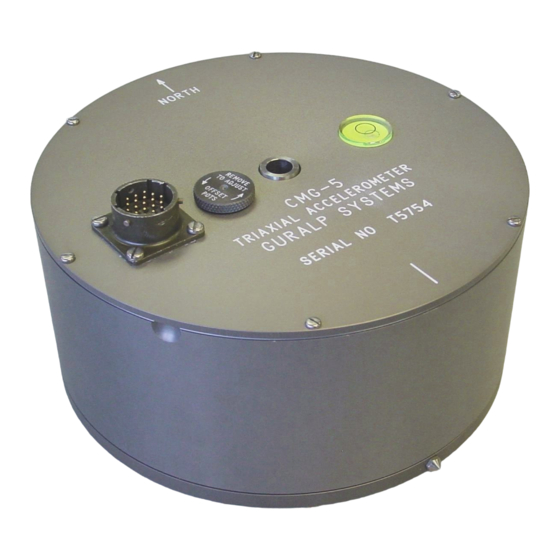
1 ° from the horizontal or vertical. You can check that the 5T is within this range by using the bubble level on the top of the casing: as long as the bubble lies completely within the scribed ring, the remaining adjustments can be made internally. -
Page 11: Electrical Connections
± 1 mV. 3.5 Electrical connections Each channel inside the 5T sensor has four output lines: a pair of differential outputs with low gain and another pair with high (around × 10) gain. Optionally, the second gain block can be configured at the factory to act as a high- pass filter to remove the DC offset at the output terminal. -
Page 12: Modifying The Sensitivity
This section applies to instruments before serial number T5225 only. The primary gain block of the 5T is normally set at × 1 (unity). If higher sensitivity is required, the gain of the instrument can be altered by inserting gain-setting resistors... -
Page 13: Calibration
Calibration 4 Calibration The 5T is supplied with a comprehensive calibration document, and it should not normally be necessary to calibrate it yourself. However, you may need to check that the response and output signal levels of the sensor are consistent with the values given in the calibration document. -
Page 14: Calibrating Accelerometers
As a result of this, the sensor output should be halved to give the true acceleration. CMG-5T instruments are tuned at the factory to produce 1 V of output for 1 V input on the calibration channel. For example, a sensor with an acceleration response of 0.25 V/ms... - Page 15 Güralp 5T Calibration you cannot see the calibration signal, zoom into the WaveView using the scaling icons at the top left of the window or the cursor keys. If you need to scale only one of the traces, right-click on the trace and select Scale..
- Page 16 Güralp 5T Calibration Returning signal strength (Z3) 701,512 counts The calibration sheets provide us with the remaining values needed to calibrate the sensor: Sensor acceleration response 0.254 V/ms Equivalent accel. from 1V calibration 1.968 ms Digitizer input port sensitivity 3.507212 µV/Bit Calibration channel sensitivity 3.491621 µV/Bit...
-
Page 17: Inside The 5T
Güralp 5T Inside the 5T 5 Inside the 5T The 5T unit is constructed of hard-anodised aluminium with “O” rings throughout, ensuring a completely waterproof housing. Inside, the mass of the vertical and horizontal components is attached to the rigid frame with parallel leaf springs. -
Page 18: The Force Transducer
In order to minimise non-linearities in the feedback force transducer, the 5T uses a symmetrical system of two magnets and two force coils. Any increase in flux in one coil is cancelled by a corresponding decrease in flux in the other, thus eliminating any non-linearity due to lack of symmetry. -
Page 19: The Sensor Transfer Function
Güralp 5T Inside the 5T The sensor transfer function Most users of seismometers find it convenient to consider the sensor as a “black box”, which produces an output signal V from a measured input x. S o long as the relationship between V and x is known, the details of the internal mechanics and electronics can be disregarded. - Page 20 Güralp 5T Inside the 5T In this equation are the roots of the numerator polynomial, giving the zeros of the transfer function, and are the roots of the denominator polynomial giving the poles of the transfer function. In the calibration pack,...
-
Page 21: Calibration Information
The 5T is designed to provide a flat response (to within 3dB) over its passband. For example, the following curve... -
Page 22: Connector Pinouts
7 Connector pinouts 7.1 5Ts with high gain output option The 5T sensor has a single connector for both power and signal output. The following details apply if the second amplification stage is being used to provide a high (10 ×) gain output channel. -
Page 23: High Pass Filter Output Option
Güralp 5T Connector pinouts 7.2 5T high pass filter output option The following table applies if the second amplification stage is being used to provide a high-pass filter (with unity gain). The same connector is used and the connector information above (in Section 7.1) applies. -
Page 24: Specifications
Güralp 5T Specifications 8 Specifications Outputs and 2 g , 1 g , 0.5 g , 0.1 g Low gain output options response Corresponding high gain 0.2 g , 0.1 g , 0.05 g , 0.01 g outputs ... -
Page 25: Revision History
Güralp 5T Revision history 9 Revision history 1009-12-14 Revised calibration section and new “internals” diagram. 2009-10-05 Additional connector information and some purely cosmetic changes 2007-11-20 Installation in hazardous environments section added. 2006-09-22 Added revision history 2006-01-06 New document MAN-050-0001 Issue E - December 2009...
Need help?
Do you have a question about the 5T and is the answer not in the manual?
Questions and answers