
Related Manuals for Güralp Affinity


Summary of Contents for Güralp Affinity
- Page 1 Affinity User's Guide Document No. MAN-AFT-0001 Issue G - December, 2019 Designed and manufactured by Güralp Systems Limited 3 Midas House, Calleva Park Aldermaston RG7 8EA England...
-
Page 2: Table Of Contents
1.2 Cautions and Notes....................5 1.3 Manuals and Software....................5 1.4 Conventions.......................5 2 Introduction........................6 2.1 Applications........................6 2.2 Key features.......................7 3 The Affinity documentation...................8 4 Getting Started........................9 4.1 Introduction........................9 4.2 Connecting to the network port.................9 4.2.1 DHCP-assigned addresses................9 4.2.2 Link-local addresses..................14 4.2.3 Assigning a static IP address................15 4.2.4 Connecting to the web interface..............18... - Page 3 Affinity 5.2.1 Connector usage summary................29 5.2.2 Connector Pin-outs..................31 6 ADC configuration......................37 6.1 Introduction......................37 6.1.1 Sample rates and decimation................37 6.2 Data acquisition configuration.................38 6.2.1 Station name/locations..................39 6.2.2 Synchronous channels..................40 6.2.3 Multiplexed channels..................41 6.2.4 Sensor parameters...................43 6.2.5 Saving and other actions.................44 Sample-clock Timing....................45 7.1 Direct GPS mode.....................46...
- Page 4 Affinity 9 ADC Calibration......................53 10 The Borehole Hanger....................54 10.1 Description......................54 10.2 Installation......................55 11 EU Declaration of Conformity..................57 12 Revision History......................58 MAN-AFT-0001 Issue G - December, 2019...
-
Page 5: Preliminary Notes
Affinity Preliminary Notes Preliminary Notes Proprietary Notice The information in this document is proprietary to Güralp Systems Limited and may be copied or distributed for educational and academic purposes but may not be used commercially without permission. Whilst every effort is made to ensure the accuracy, completeness and usefulness of the information in the document, neither Güralp Systems Limited nor any employee... -
Page 6: Introduction
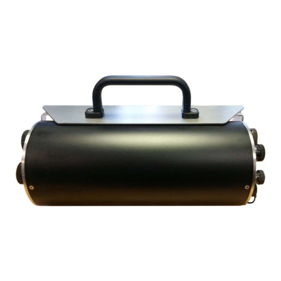
Inside the robust, waterproof, stainless steel casing is a 31-bit, high-fidelity digitiser with state-of-the-art timing precision and enhanced acquisition module capability. Designed for data quality and durability, the Güralp Affinity is a stable and robust Linux-powered unit with on-board storage and networking facilities. -
Page 7: Key Features
Affinity Introduction Key features Four low-noise 31-bit analogue-to-digital conversion (ADC) channels (three • primary plus one auxiliary) An eight-channel version is also available • Ultra-low-noise: 138 dB of dynamic range at 100 samples per second • 16 environmental multiplexed ADC channels •... -
Page 8: The Affinity Documentation
This document, MAN-AFT-0001, partially duplicates the “getting started” section of the Platinum manual and then provides details of the features which are unique to the Affinity, including configuration and operation of the built in ADCs, the PTP timing mode and the connector pin-outs. -
Page 9: Getting Started
The Güralp Affinity can be configured and monitored either over an Ethernet network or via a serial (RS232) line. If using a network, the Affinity can be accessed using a web browser or, in character mode, using ssh. Instructions for connecting to the network port are given in section 4.2 on page 9. - Page 10 - Scream will then start monitoring DHCP traffic on the local network. Power up the Affinity and allow it a minute to boot. When Scream notices a DHCP negotiation with an appropriate MAC address, it will display the allocated IP address in the window.
- Page 11 Affinity Getting Started address is pre-configured when you first install Scream. To use this feature, right- click on the multicast address and select GCFSEND:B from the context menu: All accessible Affinities (and many other GCF servers) will respond and their IP addresses will be displayed in the right-hand "Control"...
- Page 12 Guralp responder entry and clicking the associated button. From the command line, run svc guralp-responder start Once the responder service is running, Discovery will identify the Affinity on its local network. MAN-AFT-0001 Issue G - December, 2019...
- Page 13 Affinity Getting Started The entry will show the IP address of the Affinity together with limited status information. Right-clicking on the entry shows the context menu, as above, which allows you easily to reach the Affinity's web interface. Navigate to Home→Configuration→Data handling→Services and click on the guralp-responder link.
-
Page 14: Link-Local Addresses
Affinity Getting Started Registry address - This field allows specification of an alternative registry • server, if desired. Güralp own and operate the server at 52.34.40.123, which is the default, and this server is available for public use. You may prefer to operate your own registry server if, for example, your telemetry network is not connected to the public Internet. -
Page 15: Assigning A Static Ip Address
Scream's Network Control window and add a UDP server using the link-local network's broadcast address, 169.254.255.255, and start communicating immediately. If the address of the Affinity is required (for, say, web access), this can be read from Scream's control window, or in the acknowledgement window resulting from a GCFPING. - Page 16 Affinity Getting Started The following screen is displayed: Using the keys (or, on some systems, depending on your terminal type, the mouse), select whether you wish to use DHCP or static addressing. The red letters in the display indicate short-cut keys so, for example, you can, key select DHCP or to select static addressing.
- Page 17 4.2.3.1 on page 15), the web interface or gconfig. Please see the Platinum manual for more details. If you wish to connect to the Affinity from a PC, they must either both be on the same physical network and have the same network address (usually the first three numbers of the IP address) or be able to connect to each other via routers.
-
Page 18: Connecting To The Web Interface
Affinity Getting Started In the latter case, you will need to tell the Affinity the address of its default router (also known as the gateway). Issue the command: G12345 ~ # ip route add default via 192.168.0.254 substituting the address of your network's default router in place of the example address (192.168.0.254) shown. -
Page 19: Connecting To The Command Line Using Ssh
If the browser fails to connect, the most likely explanation is that the machine running the browser does not have working network communications to and from the Affinity. This can be verified by “pinging” the IP address of the browser from the command line of the Affinity: G12345 ~ # ping -c3 192.168.0.2... - Page 20 “host key”. This is normal but, if you are ever asked this again, it means that either the host key of the Affinity has changed – perhaps because of a firmware upgrade – or there is a network address conflict or, worse, a security problem on your network.
- Page 21 “Start” menu or double-clicking on its icon. You will be presented with the following screen: Enter the IP address of the Affinity into the Host Name (or IP address) field, check that SSH is selected as the Connection type and then click the button.
- Page 22 PuTTY allows you to save multiple sessions, along with a default login identity and screen colours for each. See the PuTTY manual for more details. Note: If you plan to use ssh regularly to communicate with an Affinity, you can configure the system to bypass the password prompt when logging in from a list of pre-authorised computer/user combinations.
-
Page 23: Connecting To The Serial Console
Getting Started Connecting to the Serial Console The serial console of the Affinity is accessed using the GPIO connector. The Affinity is shipped with a blue serial cable, terminating in a female DE9 connector, which can be used for console connections. -
Page 24: Logging In
Affinity name, as displayed in the prompt (G12345 in this example), will be different. Viewing data Once you know the IP address of the Affinity, it is simple to view the data using Güralp's Scream! Software. To do this: Start Scream! And choose “Network Control” from the “Windows” menu (or , which has the same effect). - Page 25 Once all desired streams are selected, key Enter to open a WaveView window showing live data streaming from the Affinity. For more details, please see the Scream! Manual, MAN-SWA-0001, which can be downloaded from http://www.guralp.com/documents/MAN-SWA-0001.pdf...
-
Page 26: Connections
Connections Connections Analogue connections The analogue connector panel of the Affinity has one or two SENSOR connectors (depending on the model) and an AUXILIARY connector. The pin-outs for these connectors are given in the following sections. Note: Early models did not provide power via the AUXILIARY connector. -
Page 27: Sensor A And Sensor B
Affinity Connections 5.1.1 SENSOR A and SENSOR B This is a standard twenty-six-pin bayonet plug, conforming to MIL-DTL-26482 (formerly MIL-C-26482). A typical part-number is 02E-16-26P although the initial “02E” varies with manufacturer. Suitable mating connectors have part-numbers like ***-16-26S and are available from Amphenol, ITT Cannon and other manufacturers. -
Page 28: Auxiliary Input
Affinity Connections 5.1.2 AUXILIARY input This is a standard nineteen-pin bayonet plug, conforming to MIL-DTL-26482 (formerly MIL-C-26482). A typical part-number is 02E-14-19P although the initial “02E” varies with manufacturer. Suitable mating connectors have part-numbers like ***-14-19S and are available from Amphenol, ITT Cannon and other manufacturers. -
Page 29: Digital Connections
Affinity Connections Digital connections The Affinity has six connectors on the digital connection panel, the pin-outs and uses of which are described in this section. 5.2.1 Connector usage summary 5.2.1.1 DATA The DATA port is a general-purpose serial port and it can also be used as alternative power input. - Page 30 The GPIO ( G eneral P urpose I nput/ O utput) port fulfils two functions: it provides a serial console to the Affinity, which can be used for monitoring, configuration and control; and it provides a number of tri-state lines which can be used to control or monitor external equipment.
-
Page 31: Connector Pin-Outs
Affinity Connections 5.2.2 Connector Pin-outs 5.2.2.1 DATA This is a standard ten-pin bayonet plug, conforming to MIL-DTL-26482 (formerly MIL-C-26482). A typical part-number is 02E-12-10P although the initial “02E” varies with manufacturer. Suitable mating connectors have part-numbers like ***-12-10S and are available from Amphenol, ITT Cannon and other manufacturers. - Page 32 Affinity Connections 5.2.2.2 ETHERNET This is a standard six-pin bayonet plug, conforming to MIL-DTL-26482 (formerly MIL-C-26482). A typical part-number is 02E-10-06P although the initial “02E” varies with manufacturer. Suitable mating connectors have part-numbers like ***-10-06S and are available from Amphenol, ITT Cannon and other manufacturers.
- Page 33 Affinity Connections 5.2.2.3 POWER This is a standard four-pin bayonet plug, conforming to MIL-DTL-26482 (formerly MIL-C-26482). A typical part-number is 02E-08-04P although the initial “02E” varies with manufacturer. Suitable mating connectors have part-numbers like ***-08-04S and are available from Amphenol, ITT Cannon and other manufacturers.
- Page 34 Affinity Connections 5.2.2.4 USB This is a standard six-pin bayonet socket, conforming to MIL-DTL-26482 (formerly MIL-C-26482). A typical part-number is 02E-10-06S although the initial “02E” varies with manufacturer. Suitable mating connectors have part-numbers like ***-10-06P and are available from Amphenol, ITT Cannon and other manufacturers.
- Page 35 Affinity Connections 5.2.2.5 GPS This is a standard ten-pin bayonet plug, conforming to MIL-DTL-26482 (formerly MIL-C-26482). A typical part-number is 02E-12-10P although the initial “02E” varies with manufacturer. Suitable mating connectors have part-numbers like ***-12-10S and are available from Amphenol, ITT Cannon and other manufacturers.
- Page 36 Affinity Connections 5.2.2.6 GPIO This is a standard twelve-pin bayonet socket, conforming to MIL-DTL-26482 (formerly MIL-C-26482). A typical part-number is 02E-14-12S although the initial “02E” varies with manufacturer. Suitable mating connectors have part-numbers like ***-14-12P and are available from Amphenol, ITT Cannon and other manufacturers.
-
Page 37: Adc Configuration
ADC configuration Introduction The Güralp Affinity contains one or two ADC cards. Each ADC card provides four full-featured, synchronous ADC channels and a single ADC with an input multiplexor that can handle eight different channels at a lower resolution. Because this style of ADC is unique to the Affinity, its configuration is not covered in the Platinum manual. -
Page 38: Data Acquisition Configuration
Data acquisition configuration The configuration interface can be used to configure the ADC in an Affinity, the digitiser module in a DM24S x EAM or any serially attached Güralp digitiser, such as a Güralp DM24 or CD24, or digital instrument. The interface for external digitisers and digital instruments is described in the Platinum manual. -
Page 39: Station Name/Locations
GCF name – these values are used for naming channels transmitted using • GCF protocols, such as Scream and BRP, or GDI. GCF system ID – this is initially based on the serial number of the Affinity ◦ but can be altered here as desired. -
Page 40: Synchronous Channels
Affinity ADC configuration 6.2.2 Synchronous channels For each of the four main synchronous channels, this section allows you to select the component letter used for stream naming, the Channel gain to be applied and the sample rate(s) to be generated. The default, recommended component lettering for a single triaxial velocity sensor is shown above. -
Page 41: Multiplexed Channels
Affinity ADC configuration The desired gain can then be selected from the drop-down menu and saved to the configuration with the button. One or more sample rates can be selected for each synchronous channel. Each selected sample rate appears in a separate row at the bottom of the table and output from each channel at that sample rate can be enabled or disabled using the check- box. - Page 42 Affinity ADC configuration button displays every channel. • For each multiplexed channel, the associated instrument and component are shown, along with a drop-down menu for selecting the sample rate and the associated automatically-generated SEED name (in S.C.N.L. format) and GCF name.
-
Page 43: Sensor Parameters
Affinity ADC configuration 6.2.4 Sensor parameters The sensor parameters table is accessed by clicking the link below the multiplexed channels table: This opens the sensors parameters table, which has one row for each input channel. Each row has: a field for Sensor gain;... -
Page 44: Saving And Other Actions
Affinity ADC configuration Note: Any specified offset is subtracted after the specified gain has been applied. Data entered into this table are stored in the file /etc/das-in/das-in.local. 6.2.5 Saving and other actions When all required changes have been made, scroll back to the top of the screen and click the button. -
Page 45: Sample-Clock Timing
CD24 or DM24 digitiser (which is, in turn, assumed to be synchronised to GPS time). For the Affinity, the recommended timing mode is Direct GPS. This offers the highest accuracy of all available options. The Platinum manual describes Direct GPS mode, NTP mode, Manual mode and CD24/DM24 with GPS modes. -
Page 46: Direct Gps Mode
Affinity Sample-clock Timing Beneath the time-zone selection button is a paragraph that specifies the currently- selected timing mode, as shown below: You can visit each of the tabbed screens without changing the mode. Each tabbed screen has its own “Set timing…” button, which saves any changes made to data in put fields on that tab and sets the relevant mode, if it has changed. -
Page 47: Diagnostics
Affinity Sample-clock Timing Below the drop-down menu are: The Service ID: The displayed ID is used as the service name for the serial • port. Restarting this service will restart the serial port's function. It is also used to name configuration files and for log messages. -
Page 48: Ptp Mode
The PTP implementation on the Güralp Affinity (ptp4l) requires that a grandmaster clock be present on the same network segment as the Affinity ( or all the routers between the grandmaster clock and the Affinity must be configured to allow... -
Page 49: Configuration
Affinity Sample-clock Timing multicast UDP packets on 224.0.1.129 and 224.0.0.107 for IPv4 or FF0x::181 and FF02::6B for IPv6). 7.2.1 Configuration From the Timing set-up screen, clicking the button displays the following configuration screen: PTP requires very little configuration. The following parameters can be adjusted: Delay mechanism: The options are: •... -
Page 50: Diagnostics
Affinity Sample-clock Timing 7.2.2 Diagnostics When in PTP mode, the main status screen acquires an extra tab displaying the PTP status: This tab simply displays the current lock status and the time that a lock was last achieved. The Data acquisition tab of the main status screen also indicates that the timing mode is PTP, in the Reference clock type field: The NTP tab also changes to show that the timing mode is PTP. -
Page 51: Digital I/O
Digital I/O Introduction The Güralp Affinity has a number of hardware lines that are typically used for power monitoring and supply, tamper detection, although they are available for other purposes if desired. These lines are monitored and controlled via the digital I/O page of the web interface. -
Page 52: System
Affinity Digital I/O 8.2.6 System This input monitors the main power supply input to the Affinity and displays the voltage being received and the current being drawn. 8.2.7 Tamper line 0 This “input” is driven by the outputs of an internal photo-detector and two micro switches which act together to indicate whether the casing has been opened. -
Page 53: Adc Calibration
ADC Calibration ADC Calibration The ADC of each Güralp Affinity is calibrated at the factory. All measurements made are traceable to national standards and conform to the requirements of ISO/IEC 17025:2005. The calibration values are stored on the system and used to automatically scale every channel to an input sensitivity (bit-weight) of 1µV per... -
Page 54: The Borehole Hanger
10.1 Description The Affinity Borehole Hanger is a welded steel frame, which is designed to fit into the top of a borehole casing, in place of a trap plate. It is made to securely carry an Affinity unit flush with the top of the borehole casing. -
Page 55: Installation
Affinity. 4. Remove the trap plate from the top of the hanger frame. - Page 56 Affinity The Borehole Hanger 8. Connect the signal cable to the Affinity digitiser and lower it into the hanger frame. Engage the two pins on the frame lower plate with the peg holes in the end bulkhead of the Affinity. This may be facilitated by connecting one or two of the system cables to the top of the Affinity and using their connectors for purchase.
-
Page 57: Eu Declaration Of Conformity
READING, RG7 8EA. Tel: +44 118 981 9056 E-mail: technical@guralp.com Declare under our sole responsibility that the following product Equipment name: Affinity Model Number: AFF-3208SS0VE0643 and appropriate variants Is in conformity with the Electromagnetic Compatibility Directive 2014/30/EU Low Voltage Directive 2014/35/EU... -
Page 58: Revision History
Affinity Revision History Revision History 2021-09-09 Added EU Declaration of Conformity 2019-06-25 Added sensor control lines logic-level autodetection. Refreshed screen-shots for W10. Mentioned configurable instrument types. Added guralp/responder/Discovery details. 2019-06-18 Modified GPIO connector pin-out to add pin L (connected to F).
Need help?
Do you have a question about the Affinity and is the answer not in the manual?
Questions and answers