Table of Contents
Advertisement
Operation/Repair/Parts
Electric Airless Sprayers
For professional use only.
Not approved for use in explosive atmospheres or hazardous locations.
For the application of architectural paints and coatings.
MP 455, Mustang 4850 Models:
3300 psi (22.7 MPa, 227 bar) Maximum Working Pressure
Important Safety Instructions
Read all warnings and instructions in this manual and in related manuals.
Be familiar with the controls and the proper usage of the equipment.
Save these instructions.
Related Manuals:
3A4133
Gun
3A4347
Pump
www.graco.com/techsupport
3A4180C
EN
ti29449a
Advertisement
Table of Contents

Subscribe to Our Youtube Channel
Related Manuals for AIRLESSCO MP 455


Summary of Contents for AIRLESSCO MP 455
- Page 1 For professional use only. Not approved for use in explosive atmospheres or hazardous locations. For the application of architectural paints and coatings. MP 455, Mustang 4850 Models: 3300 psi (22.7 MPa, 227 bar) Maximum Working Pressure Important Safety Instructions Read all warnings and instructions in this manual and in related manuals.
-
Page 2: Table Of Contents
Technical Specifications ......41 Airlessco Standard Warranty ......43... -
Page 3: Models
Models Models Hi-Boy Stand Model MP455 17M132 17M133 Mustang 4850 17M149 17M150 Asia/ANZ/ MP455 17M235 17M236 South America 3A4180C... -
Page 4: Warnings
Warnings Warnings The following warnings are for the setup, use, grounding, maintenance, and repair of this equipment. The exclamation point symbol alerts you to a general warning and the hazard symbols refer to procedure-specific risks. When these symbols appear in the body of this manual or on warning labels, refer back to these Warnings. - Page 5 Warnings SKIN INJECTION HAZARD High-pressure spray is able to inject toxins into the body and cause serious bodily injury. In the event that injection occurs, get immediate surgical treatment. • Do not aim the gun at, or spray any person or animal. •...
- Page 6 Warnings FIRE AND EXPLOSION HAZARD Flammable fumes, such as solvent and paint fumes, in work area can ignite or explode. To help prevent fire and explosion: • Do not spray flammable or combustible materials near an open flame or sources of ignition such as cigarettes, motors, and electrical equipment.
- Page 7 Warnings ELECTRIC SHOCK HAZARD This equipment must be grounded. Improper grounding, setup, or usage of the system can cause electric shock. • Turn off and disconnect power cord before servicing equipment. • Connect only to grounded electrical outlets. • Use only 3-wire extension cords. •...
-
Page 8: Component Identification
Component Identification Component Identification Stand Models ti29450a Trigger Lock ON/OFF Switch M Drain Tube Pressure Control Fluid Intake Two-Finger Trigger Conversion Kit Pump Prime Valve Fluid Outlet Tip Guard Power Cord Wrap Spray Tip Filter (inside manifold) Finger Guard / TSO Fill Point Airless Hose Model/Serial Tag (Not shown, located Power Cord... -
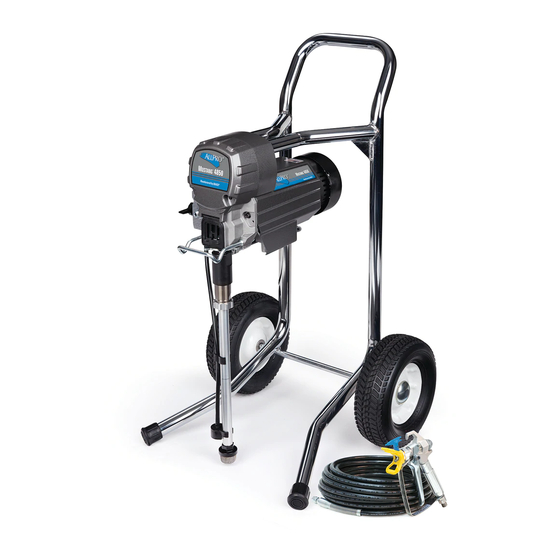
Page 9: Hi-Boy Models
Component Identification Hi-Boy Models ti29451a Trigger Lock ON/OFF Switch M Drain Tube Pressure Control Fluid Intake Two-Finger Trigger Conversion Kit Pump Prime Valve Fluid Outlet Tip Guard Filter (inside manifold) Spray Tip Finger Guard / TSO Fill Point Pail Hook Airless Hose Model/Serial Tag (Not shown, located Power Cord... -
Page 10: Grounding
Grounding Grounding The equipment must be grounded to reduce the risk of static sparking and electric shock. An electric or static spark can cause fumes to ignite or explode. An improper ground can cause electric shock. A good ground provides an escape wire for the electric current. -
Page 11: Pressure Relief Procedure
Pressure Relief Procedure Pressure Relief Procedure Turn pressure control to lowest setting. Follow the Pressure Relief Disengage the trigger lock. Procedure whenever you see this symbol. ti29454a Hold a metal part of the gun firmly to a grounded metal pail. Trigger the gun to This equipment stays pressurized until relieve pressure. -
Page 12: Trigger Lock
Pressure Relief Procedure Trigger Lock Engage the trigger lock. Put drain tube in a pail. Turn prime valve Always engage the trigger lock when sprayer down. Leave prime valve in down (drain) is stopped to prevent the gun from being position until you are ready to spray triggered accidentally by hand or if dropped again. -
Page 13: Setup
Setup Setup Use wrenches to tighten securely. Engage trigger lock. When unpacking sprayer for the first time or after long term storage perform setup procedure. When first setup is performed remove shipping plug from fluid outlet. Connect airless hose to fluid outlet. Use ti29455a wrenches to tighten securely. - Page 14 Setup When unpacking sprayer for the first Squeeze bottle to dispense enough time remove packaging materials from TSO to fill the space between the inlet strainer. After long term storage pump rod and packing nut seal. check inlet strainer for clogs and debris. ti29460a Make certain ON/OFF switch is OFF.
- Page 15 Setup 10. Turn prime valve down. 15. Turn prime valve horizontal. Disengage trigger lock. ti29461a 11. Place fluid intake with drain tube in grounded metal pail partially filled with flushing fluid. See Grounding, page 11. NOTE: New sprayers are shipped with storage fluid that must be flushed out with mineral spirits prior to using the sprayer.
-
Page 16: Startup
Startup Startup Turn pressure control 1/2 turn to start motor. Allow paint to circulate through sprayer until paint flows out the drain tube. Perform Pressure Relief Procedure, page 12. Turn pressure control to lowest pressure. ti29464a Turn prime valve horizontal. Disengage trigger lock. - Page 17 Startup Hold gun against grounded metal waste pail. Trigger gun until paint appears. High-pressure spray is able to inject toxins into the body and cause serious bodily injury. Do not stop leaks with hand or rag. Inspect for leaks. If leaks occur, perform Pressure Relief Procedure, page 12, then tighten all fittings and repeat Startup procedure.
-
Page 18: Operation
Operation Operation Spray Tip Installation Spray Spray test pattern. Adjust pressure to eliminate heavy edges. To avoid serious injury from skin injection do not put your hand in front of the spray tip when installing or removing the spray tip and tip guard. -
Page 19: Clear Tip Clog
Operation Clear Tip Clog Cleanup In the event that particles or debris clog the spray tip, this sprayer is designed with a Perform Pressure Relief Procedure, reversible spray tip that quickly and easily page 12. clears the particles without disassembling the sprayer. - Page 20 Operation Place fluid intake in flushing fluid. Use While continuing to trigger gun, turn water for water base paint and mineral prime valve down. Then, release gun spirits for oil-based paint. Place drain trigger. Allow flushing fluid to circulate tube in waste pail. until fluid comes out of drain tube clear.
- Page 21 Operation 12. Turn pressure control knob to the lowest 14. If flushing with water, flush again with pressure setting and turn ON/OFF mineral spirits or Pump Conditioner to switch to OFF position. Disconnect leave a protective coating to prevent power to sprayer. freezing or corrosion.
-
Page 22: Maintenance
Maintenance Maintenance Routine maintenance is important to ensure proper operation of your sprayer. Maintenance includes performing routine actions which keep your sprayer in operation and prevents trouble in the future. Activity Interval Inspect/clean sprayer filter, fluid inlet strainer, and gun Daily or each time you spray filter. -
Page 23: Troubleshooting
Troubleshooting Troubleshooting Mechanical/Fluid Flow Follow Pressure Relief Procedure, Check all possible problems and causes page 12, before checking or repairing. before disassembling the unit. What to Check What to Do If check is OK, go to next When check is not OK, Problem check refer to this column... - Page 24 Troubleshooting What to Check What to Do If check is OK, go to next When check is not OK, Problem check refer to this column Pump output is low Pump rod damage. Repair pump. See pump manual. Low stall pressure. Turn pressure knob fully clockwise.
- Page 25 Troubleshooting What to Check What to Do If check is OK, go to next When check is not OK, Problem check refer to this column Fluid is spitting from gun Air in pump or hose. Check and tighten all fluid connections.
-
Page 26: Electrical
Troubleshooting Electrical Symptom: Sprayer does not run, stops Turn the ON/OFF switch OFF wait 30 running, or will not shut off. seconds and then turn power back ON again (this ensures sprayer is in normal run mode). Turn pressure control knob clockwise 1/2 turn. - Page 27 Troubleshooting Problem What to Check How to check Check motor rotation. Perform a spin test by connecting a 9 –12 Volt battery to the motor leads. Motor leads may vary in style and size. Locate the two wires going to the carbon brushes normally Red and Black.
- Page 28 Troubleshooting Problem What to Check How to check Check motor armature resistance. Connect the Red and Black leads from the motor to an Ohm meter. Rotate the motor while checking for opens. If an open is found replace the motor. BLACK (-) RED (+) YELLOW...
- Page 29 Troubleshooting Problem What to Check How to check Sprayer will not shut off after Check pressure control. Disconnect pressure control, if reaching or exceeding maximum sprayer still runs, replace control pressure. board. If the sprayer stops, replace pressure control. Basic electrical problems Motor leads are securely fastened Replace loose terminals;...
-
Page 30: Stand Sprayer Parts
Stand Sprayer Parts Stand Sprayer Parts Ref. Torque 140-160 in-lb (15.8 - 18.1 N•m) 30-35 in-lb (3.4 - 4.0 N•m) 23-27 in-lb (2.6 - 3.1 N•m) ti29477a See page 37 3A4180C... -
Page 31: Stand Sprayer Parts
Stand Sprayer Parts Stand Sprayer Parts Ref. Torque 140-160 in-lb (15.8 - 18.1 N•m) Hammer tight 23-27 in-lb (2.6 - 3.1 N•m) 65 22 14 4 ti29478a 3A4180C... -
Page 32: Stand Sprayers Parts List
Stand Sprayer Parts Stand Sprayers Parts List Description Ref. Part Qty. Description Ref. Part Qty. 115495 SCREW, mach, hex 107434 BEARING, thrust washer hd 115498 SCREW, mch, See page LABEL, front slot/hex, wash hd 116073 WASHER, thrust See page LABEL, side 116074 WASHER, thrust 116079... -
Page 33: Hi-Boy Sprayers Parts
Hi-Boy Sprayers Parts Hi-Boy Sprayers Parts Ref. Torque 140-160 in-lb (15.8 - 18.1 N•m) 30-35 in-lb (3.4 - 4.0 N•m) 23-27 in-lb (2.6 - 3.1 N•m) 23 95 ti29480a See page 37 3A4180C... -
Page 34: Hi-Boy Sprayers Parts
Hi-Boy Sprayers Parts Hi-Boy Sprayers Parts Ref. Torque 140-160 in-lb (15.8 - 18.1 N•m) Hammer tight 23-27 in-lb (2.6 - 3.1 N•m) ti29479a 3A4180C... -
Page 35: Hi-Boy Sprayers Parts List
Hi-Boy Sprayers Parts Hi-Boy Sprayers Parts List Ref. Description Part Qty. Ref. Description Part Qty. See page LABEL, side 107434 BEARING, thrust 115498 SCREW, mch, 54 * KIT, motor, electric slot/hex, wash hd includes 54a 116073 WASHER, thrust 17C794 120V 116074 WASHER, thrust 17C799... -
Page 36: Accessories And Labels
Accessories and Labels Accessories and Labels Ref. 34 Ref. 63 Ref. 65 Card, Ref. 53 Label, Label, Medical Ref. 52 Label, Danger Warning Alert Sprayer Model Label, Front Side 17M132 17M688 17M695 15K359 # 195793 & 179960 # 17M133 17M149 17M706... -
Page 37: Control Box And Filter
Control Box and Filter Control Box and Filter Ref. Torque 140-160 in-lb (15.8 - 18.1 N•m) 30-35 in-lb (3.4 - 4.0 N•m) 130-150 in-lb (14.7-16.9 N•m) 320-380 in-lb (36.2-42.9 N•m) ti29481a 3A4180C... -
Page 38: Control And Filter Parts List
Control Box and Filter Control and Filter Parts List Ref. Part Description Qty. Ref. Part Description Qty. 49a 24R905 BOARD, capacitor, 111600 PIN, grooved 230V 277364 GASKET, seat, valve 15A464 LABEL, control 117501 SCREW, mach, hex CORD, power washer hd 15J743 120V models 17M398... -
Page 39: Wiring Diagrams
Wiring Diagrams Wiring Diagrams 120V from Motor Red (+) 2 x Yellow Black (-) Replaceable Fuse Pressure Control Assembly ON/OFF Switch ti5643a Black Capacitor Power White Plug Green ti5643a 3A4180C... -
Page 40: 230V
Wiring Diagrams 230V From Motor Red (+) 2X Yellow Black (-) Pressure Control Assembly Replaceable Fuse Red (D) Black (E) ON/OFF switch Capacitors Blue Black (F) Brown Red (H) Green Red MOV Power Plug ti22267b 3A4180C... -
Page 41: Technical Specifications
Technical Specifications Technical Specifications MP 455 / Mustang 4850 Metric Sprayer Maximum fluid working pressure 3300 psi 228 bar, 22.8 MPa Maximum Delivery 0.47 gpm 1.8 lpm Maximum Tip Size 0.021 0.021 Fluid Outlet 1/4 in. npsm 1/4 in. npsm... - Page 42 Notes Notes 3A4180C...
-
Page 43: Airlessco Standard Warranty
With the exception of any special, extended, or limited warranty published by Airlessco, Airlessco will, for a period of twelve months from the date of sale, repair or replace any part of the equipment determined by Airlessco to be defective. This warranty applies only when the equipment is installed, operated and maintained in accordance with Airlessco’s written recommendations. - Page 44 All written and visual data contained in this document reflects the latest product information available at the time of publication. Airlessco reserves the right to make changes at any time without notice. Original Instructions. This manual contains English. MM 3A4180 GRACO INC.
Need help?
Do you have a question about the MP 455 and is the answer not in the manual?
Questions and answers