
Related Manuals for Shindaiwa CL590


Summary of Contents for Shindaiwa CL590
- Page 1 1Cover ENGLISH (Original instructions) OPERATOR'S MANUAL GRASS-TRIMMER/BRUSHCUTTER CL590 WARNING READ THE INSTRUCTIONS CAREFULLY AND FOLLOW THE RULES FOR SAFE OPERATION. FAILURE TO DO SO COULD RESULT IN SERIOUS INJURY.
- Page 2 Always keep your manual in a place where it is readily accessible. If you have lost your manual or it is damaged and no longer readable, please purchase a new one from your shindaiwa dealer.
-
Page 3: Table Of Contents
Contents For safe use of your product....................4 Warning notices ......................4 Other indicators ......................4 Symbols ......................... 4 Location in which a safety decal is attached..............6 Handling fuel........................7 Handling the engine....................... 8 Handling the product ..................... 9 Packing list........................ -
Page 4: For Safe Use Of Your Product
For safe use of your product For safe use of your product Be careful to read this section before using your product. The precautions described in this section contain important safety information. Please observe them carefully. You must also read the precautions that appear in the body of the manual itself. Text following a [diamond mark] mark describes the potential consequences of failing to observe the precaution. - Page 5 For safe use of your product Symbol form/shape Symbol description/applica- Symbol form/shape Symbol description/applica- tion tion Carburettor adjustment Waring, side thrust - High speed mixture Usage without shield not per- Carburettor adjustment mitted - Idle speed Usage of metal blades not U-handle permitted Usage of nylon line cutting...
-
Page 6: Location In Which A Safety Decal Is Attached
For safe use of your product Location in which a safety decal is attached The safety decal shown below has been attached to the products described in this manual. Ensure that you understand what the decal means before using your product. If the decal becomes unreadable due to wear and tear or damage, or peels off and is lost, please purchase a replacement decal from your dealer and attach it in the location shown in the illustrations below. -
Page 7: Handling Fuel
For safe use of your product Handling fuel DANGER Always keep well away from fire when refuelling Fuel is highly inflammable and leads to a risk of fire if mishandled. Use extreme care when mixing, storing or handling or serious personal injury may result. Be careful to observe the following instructions. Do not smoke or hold a flame near when refuelling. -
Page 8: Handling The Engine
For safe use of your product Handling the engine WARNING Starting the engine Exhaust fumes are toxic Be particularly careful to observe the following precau- The exhaust fumes from the engine contain toxic gases. tions when starting the engine: Do not operate the product indoors or in other ill venti- Check that none of the nuts and bolts are loose lated places. -
Page 9: Handling The Product
For safe use of your product Handling the product General precautions WARNING Operator's manual Loaning or assigning your product Be careful to read the operator's manual When loaning your product to another party, ensure properly before using your product in or- that the person borrowing the product receives the op- der to ensure correct operation. - Page 10 For safe use of your product WARNING Users of the product Vibration and cold The product should not be used by: It is believed that a condition called Raynaud's Phenome- people who are tired non which affects the fingers of certain individuals may be people who have taken alcohol brought about by exposure to vibration and cold.
- Page 11 For safe use of your product WARNING Remove foreign objects and obstructions before working with the product Before starting work, check the area where you will be working and re- move any small stones and empty cans likely to ricochet off the cutting attachment, as well as any pieces of string or wire that might become twisted around the cutting attachment.
- Page 12 For safe use of your product Precautions concerning the cutting attachment DANGER Always stop the engine when a cutting attachment jam occurs. Do not attempt to remove an object causing a jam if the engine is running. Severe injury can occur if a jam is removed and the cutting attachment suddenly starts. 1.With metal blade WARNING Use correct blades...
- Page 13 For safe use of your product Protective gear WARNING Wear protective gear Always wear the following protective gear when working with the trimmer. a Head protection (helmet): Protects the head b Ear muffs or ear plugs: Protect the hearing c Safety goggles: Protect the eyes d Face shield: Protects the face e Safety gloves: Protect the hands from cold and vibration f Work clothes that fit (long sleeves, long trousers): Pro-...
-
Page 14: Packing List
Packing list Packing list The following parts are packed separately in the packing box. When you have unpacked the box, please check the parts that it contains. Contact your dealer if anything is missing or broken. Engine Operation Shaft 1. Engine and right handle 12. -
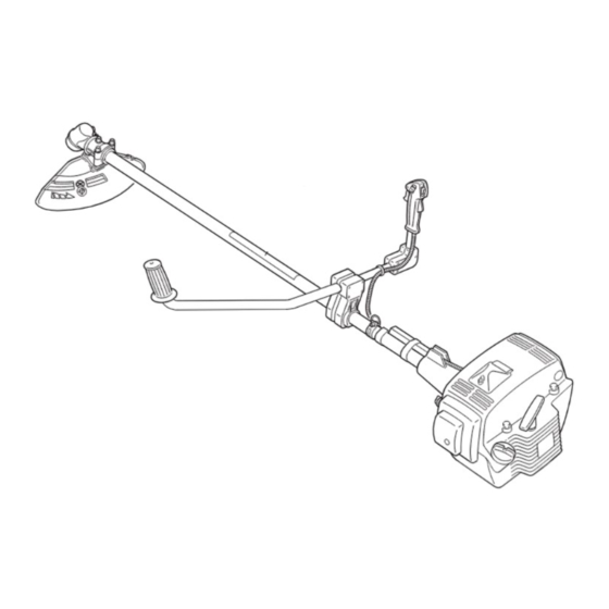
Page 15: Description
Description Description 1. Angle transmission Having two gears to change to an- 9. Throttle trigger lockout Locks throttle trigger in the idling gle of rotating axis. position until you have a proper grip with your right hand 2. Blade cover When transporting the unit, use the appro- around the handle. -
Page 16: Before You Start
Before you start Before you start Assembly WARNING Read the operator's manual carefully to ensure that you assemble the product correctly. Using a product that has been incorrectly assembled could lead to an accident or serious injury. Stand assembly Fasten the stand to the operation shaft. 1. - Page 17 Before you start Install the right handle in the bracket. Position the handle in comfortable operating position and tighten bolts (M5×25). 1. Bracket 3. Bolt M5×25 2. Right handle Using a socket wrench, open the cable guide cover. 1. Cable guide 2.
- Page 18 Before you start Installation of bracket Fit bracket to mounting portion of angle transmission and fix the bracket by holding fitting plate pressed from beneath and tighten 4 bolts (M5×25) lightly. Get notches and convexes of fitting plate to face corresponding convexes and concaves of bracket, and fix bracket tightening 4 bolts (M5×25) securely.
- Page 19 Before you start Installing blade Inspect blades before installation. Check for sharpness. Dull blades increase the risk of blade kickback reactions. Small cracks can develop into fractures resulting in a piece of blade flying off during operation. Discard cracked blades no matter how small the crack. Blade retainer, blade, lower blade retainer, cup and nut finger tight.
-
Page 20: Adjusting The Balance
Before you start Adjusting the balance Adjusting the shoulder harness WARNING This product is designed to fit a wide variety of body sizes, but may not be adjustable for extremely tall persons. Do not use the unit if your feet can reach the cutting attachment when the unit is attached to the harness. IMPORTANT A person's size can affect the balancing adjustment. -
Page 21: Preparing The Fuel
10 % of ethyl alcohol. Recommended mixture ratio; 50 : 1 (2 %) for ISO-L-EGD Standard (ISO/CD 13738), JASO FC,FD grade and shindaiwa 50 : 1 oil. - Do not mix directly in engine fuel tank. -
Page 22: Engine Operation
Engine operation Engine operation Starting the engine WARNING When starting the engine, observe the precautions described from Page 4 in the section "For safe use of your prod- uct" to ensure that you operate the product correctly. If the cutting attachment rotates even though the throttle trigger is in the idle speed position when the engine is start- ed, adjust the carburettor before using the product. - Page 23 Engine operation Checking that the area around you is safe, hold the position closest to the engine firmly as shown in the illustration, pull- ing several times on the starter grip. If you hear an explosion-like sound and the engine stops im- mediately, move the choke knob to the Open position and continue pulling on the starter grip to start the engine.
-
Page 24: Stopping The Engine
Engine operation Stopping the engine Move the throttle trigger to the idle speed position and set the engine to idling (i.e. low speed). Move the ignition switch to the Stop position. In the event of an emergency, stop the engine immediately using the ignition switch. -
Page 25: Trimming Operation
Trimming operation Trimming operation DANGER Always stop the engine when a cutting attachment jam occurs. Do not attempt to remove an object causing a jam if the engine is running. Severe injury can occur if a jam is removed and the cutting attachment suddenly starts. Never attempt to operate the product with one hand. - Page 26 Trimming operation Trimming This is feeding the trimmer carefully into the material you wish to cut. Tilt the head slightly to direct the debris away from you. If cut- ting up to a barrier such as a fence, wall or tree, approach from an angle where any debris ricocheting off the barrier will fly away from you.
-
Page 27: Basic Trimming Operation With Metal Blade
Trimming operation Always wear proper eye protection against thrown objects. Objects can bounce up at you from the ground under the shield, or ricochet off any nearby hard surface. Do not trim at high speed near roadways when there is traffic, or in places where there are pedestrians. - Page 28 Trimming operation Using shoulder harness Buckle waist belt. Belt should be snug. Attach product to harness. Check for correct adjustment by moving cutting attachment along ground. Re-adjust position of suspension point if necessary. Place shoulder harness over both shoulders and adjust straps so the connecting point latch as shown.
-
Page 29: Precautions To Observe When Working
Trimming operation Reaction forces Push. The operator may feel the unit push toward him when he tries to cut the object on right. If he cannot hold the blade in the cut, a kickback may occur when the blade is pushed out to where the teeth at the outside furthest point from the operator are cutting. - Page 30 Trimming operation When you turn off the engine, check to ensure that the trimmer blade has stopped rotating before you lower the product to the ground. Even if the engine has been turned off, the blade can still cause an injury while free-wheeling. The silencer will remain hot for some time after the engine has been turned off.
-
Page 31: Maintenance And Care
Maintenance and care Maintenance and care Servicing guidelines Area Maintenance Page Before use Monthly Air filter Clean/Replace • Fuel filter Inspect/Clean/Replace • Spark plug Inspect/Clean/Adjust/Replace • Carburettor Adjust/Replace and adjust • Cooling system Inspect/Clean • Silencer Inspect/Tighten/Clean • Drive shaft Grease •** Angle transmission... - Page 32 Maintenance and care Replacing fuel filter Use a piece of metal wire or the like to pick up fuel filter through fuel tank opening. Pull old filter from fuel line. Install new fuel filter. NOTE If filter is excessive dirty or no longer fits properly, replace it. 1.
- Page 33 Maintenance and care Cooling system maintenance IMPORTANT To maintain proper engine operating temperature, cooling air must pass freely through the cylinder fin area. This flow of air carries combustion heat away from the engine. Overheating and engine seizure can occur when: Air intakes are blocked, preventing cooling air from reaching the cylinder, Dust and grass build up on the out side of the cylinder.
- Page 34 Maintenance and care Check spark plug Check plug gap. Correct gap is 0.6 mm to 0.7 mm. Inspect electrode for wear. Inspect insulator for oil or other deposits. Replace plug if needed and tighten to 15 N·m - 17 N·m (150 kgf·cm to 170 kgf·cm).
- Page 35 Maintenance and care When the cutting blade becomes dull due to wear reverse it for further use. When chip or bend occurs on the blade, vibration will increase. Replace with new one. When filing the blade file 3 cutting edges evenly using a flat file as shown in the illustration.
- Page 36 Maintenance and care Troubleshooting table Problem Diagnosis Cause Solution The engine does There is no fuel in the fuel tank Fuel supply not start The stop switch is in the Stop position Move to the Start po- Excess fuel suction sition Electrical fault Start the engine after...
-
Page 37: Storage
Storage Storage Long-term storage (30 days or more) WARNING Do not store in sealed locations filled with fuel gas, or close to naked flames or sparks. You could cause a fire. When storing the product for long periods of time (30 days or more), ensure that the following preparations for stor- age are carried out. -
Page 38: Specifications
10 % of ethyl alcohol. Two stroke, air-cooled engine oil. ISO-L-EGD Stand- ard (ISO/CD 13738), JASO FC,FD grade and shindaiwa 50 : 1 oil. Ratio 50 : 1 (2%) Fuel consumption at maximum engine power 1.77... -
Page 39: Declaration Of Conformity
JAPAN declares that the hereunder specified new unit: GRASS-TRIMMER/BRUSHCUTTER Brand: shindaiwa Type: CL590 complies with: * the requirements of Directive 98/37/EC (1998)and 2006/42/EC: from 29th December 2009 (use of harmonized stand- ard ISO 11806 (EN 31806)) * the requirements of Directive 2004/108/EC (use of harmonized standard EN ISO 14982) - Page 40 1Notes and rear cover 7-2 SUEHIROCHO 1-CHOME, OHME, TOKYO 198-8760, JAPAN PHONE: 81-428-32-6118. FAX: 81-428-32-6145. X750-012 79 2 Printed in Japan 0x0xxxx zzzz ES X750 226-470 2 © 2009...