Table of Contents
Advertisement
Quick Links
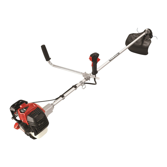
GRASS TRIMMER
/ BRUSH CUTTER
The engine exhaust from this product contains chemicals
known to the State of California to cause cancer, birth defects,
or other reproductive harm.
Read and understand all provided literature before use.
Failure to do so could result in serious injury.
Note: This product complies with CAN ICES-2/NMB-2.
X7502341302
02/21
©
ECHO Incorporated
Operator's
Manual
C262
Advertisement
Table of Contents

Subscribe to Our Youtube Channel
Related Manuals for Shindaiwa C262


Summary of Contents for Shindaiwa C262
- Page 1 Operator’s Manual C262 GRASS TRIMMER / BRUSH CUTTER The engine exhaust from this product contains chemicals known to the State of California to cause cancer, birth defects, or other reproductive harm. Read and understand all provided literature before use. Failure to do so could result in serious injury.
-
Page 2: Table Of Contents
TABLE OF CONTENTS C262 TABLE OF CONTENTS Introduction ....................4 Servicing Information .................. 4 Parts/Serial Number................4 Service ....................5 Consumer Product Support ..............5 Product Registration ................5 Additional Literature ................5 Safety ......................6 Manual Safety Symbols and Important Information ......6 International Symbols ................ - Page 3 C262 TABLE OF CONTENTS Cooling System ................. 43 Exhaust System ................44 Carburetor Adjustment ..............46 Lubrication ..................47 Nylon Line Replacement ..............48 Sharpening Metal Blades ..............49 Troubleshooting ..................51 Storage ..................... 53 Long Term Storage (Over 30 Days) ..........53 Specifications ...................
-
Page 4: Introduction
SERVICING INFORMATION Parts/Serial Number Genuine SHINDAIWA Parts and Assemblies for your SHINDAIWA products are available only from an Authorized SHINDAIWA Dealer. When you do need to buy parts always have the Model Number and Serial Number of the unit with you. -
Page 5: Service
Service Service of this product during the warranty period must be performed by an Authorized SHINDAIWA Service Dealer. For the name and address of the Authorized SHINDAIWA Service Dealer nearest you, ask your retailer or call: 1-877-986-7783. Dealer information is also available on WWW.SHINDAIWA-USA.COM. -
Page 6: Safety
SAFETY C262 SAFETY Manual Safety Symbols and Important Information Throughout this manual and on the product itself, you will find safety alerts and helpful, informational messages preceded by symbols or key words. The following is an explanation of those symbols and key words and what they mean to you. -
Page 7: International Symbols
C262 SAFETY International Symbols Symbol Description Symbol Description Warning, See Carburetor Operator’s Adjustment - High Manual Speed Mixture Wear Eye, Ear Carburetor and Head Adjustment - Idle Protection Speed Wear Hand Carburetor and Foot Adjustment - Low Protection Speed Mixture... -
Page 8: Personal Condition And Safety Equipment
SAFETY C262 Symbol Description Symbol Description Beware of blade Do not use blades. thrust String line only. Do not use string line. Blades only. Personal Condition and Safety Equipment Cancer and Reproductive Harm www.P65Warnings.ca.gov The muffler or catalytic muffler and surrounding cover may become extremely hot. - Page 9 C262 SAFETY Users of this product risk injury to themselves and others if the unit is used improperly and/or safety precautions are not followed. Proper clothing and safety gear must be worn when operating unit. Physical Condition Your judgment and physical dexterity may not be good: •...
- Page 10 SAFETY C262 Proper Clothing Wear snug-fitting, durable clothing: • Pants should have long legs, shirts should have long sleeves. • DO NOT WEAR SHORTS. • DO NOT WEAR TIES, SCARVES, JEWELRY, or clothing with loose or hanging items that could become entangled in moving parts or surrounding growth.
- Page 11 C262 SAFETY It is believed that a condition called Raynaud’s Phenomenon, which affects the fingers of certain individuals, may be brought about by exposure to vibration and cold. Exposure to vibration and cold may cause tingling and burning sensations, followed by loss of color and numbness in the fingers.
- Page 12 SAFETY C262 • Immediately stop using all power equipment and consult a doctor if you feel tingling, numbness, or pain in the fingers, hands, wrists, or arms. The sooner RSI/CTS is diagnosed, the more likely permanent nerve and muscle damage can be prevented.
-
Page 13: Equipment
C262 SAFETY Equipment Use only approved attachments. Serious injury may result from the use of a non-approved attachment combination. ECHO INC. will not be responsible for the failure of cutting devices, attachments or accessories which have not been tested and approved by ECHO INC. - Page 14 SAFETY C262 Check wiring and connectors for nicks, cuts, exposed wire, ◆ or other damage, and repair or replace as needed. Exposed wire or connectors can cause shocks, sparks, and risk of fire or explosion, resulting in serious injury. Check wire terminals for secure connections.
-
Page 15: Emission Control (Exhaust & Evaporative)
C262 EMISSION CONTROL EMISSION CONTROL (EXHAUST & EVAPORATIVE) CARB And EPA Emissions Control Information The emission control system for the engine is EM (engine modification) and, if the second to last character of the Engine Family on the Emission Control Information label (sample below) is “B”, “C”, “K”, or “T”, the emission... -
Page 16: Description
Locate the safety decal(s) on your unit. Make sure the decal(s) is legible and that you understand and follow the instructions on it. If a decal cannot be read, a new one can be ordered from your SHINDAIWA dealer. Safety label is for example only. Your label my appear slightly different. - Page 17 C262 DESCRIPTION Spark Plug Arm Rest Spark Arrestor Muffler Or Spark Arrestor Muffler With Catalyst Fuel Tank Fuel Tank Cap Recoil Starter Handle Purge Bulb Choke Air Cleaner 10. Debris Shield With Cut-off Knife 11. Debris Shield Without Cut-off Knife 12.
-
Page 18: Contents
Due to packaging restrictions, some assembly may be necessary. After opening the carton, check for damage. Immediately notify your retailer or SHINDAIWA Dealer of damaged or missing parts. Use the contents list to check for missing parts. Power Head / Drive Shaft Assembly U-handle Assembly Operator’s Manual... -
Page 19: Assembly
C262 ASSEMBLY ASSEMBLY U-Handle Installation Parts Required: U-Handle, upper u-handle clamp, 4 u-handle bolts Position u-handle as shown and install upper u-handle clamp (A) and secure with 4 u- handle bolts (B). Route throttle linkage and ignition lead assembly along shaft and clip as shown. -
Page 20: Blade Installation
ASSEMBLY C262 Note: The throttle linkage must be adjusted by moving the adjustment nut (D). Consult with your dealer for correct adjustment procedure. Tighten nut (E). Connect 2 ignition stop leads (F, G) from throttle cable assembly to 2 ignition leads (F, G) on engine. - Page 21 C262 ASSEMBLY Shield Installation (blade operation) Parts Required: Shield without cutoff knife If installed remove nylon line head and shield with cutoff knife. Align hole in upper plate with notch in edge of gear housing and insert head locking tool (H).
- Page 22 ASSEMBLY C262 Slide shield without cut off knife (M) onto shield base. Secure shield with bolt and nut (J,K). Install Blade Parts Required: Upper Plate, Lower Plate, 10 mm Nut with Left Hand threads, 2 x 25 mm Cotter Pin, Blade.
-
Page 23: Shield Installation
C262 ASSEMBLY Shield Installation (Nylon line head operation) Parts Required: Shield with cutoff knife Shield with cutoff knife is for use with the Nylon Line Head only. Install shield without cutoff knife when using plastic or metal blades, or serious injury may result. -
Page 24: Nylon Line Head Installation
ASSEMBLY C262 Nylon Line Head Installation Parts Required: Nylon Line Head. Wear Gloves or personal injury may result: Cutoff knife is sharp. ◆ Gearcase and surrounding area may be hot. ◆ Make sure shield with cutoff knife and upper plate are properly installed. -
Page 25: Balance And Adjust Unit
C262 OPERATION Balance and Adjust Unit Loosen harness clamp screw. Put on harness and attach unit to harness. Slide harness clamp up (A) or down until unit balances with head approximately 50-75 mm (2-3 in.) from the ground. Tighten harness clamp screw. -
Page 26: Operation With Blades
OPERATION C262 Operation With Blades Metal blades are very sharp and can cause severe injuries, even if engine is off and blades are not moving. Avoid contact with blades. Wear gloves to protect hands. Blade use demands specific brush cutter configuration. -
Page 27: Blade Selection
C262 OPERATION Note: The barrier bar is used to restrict rearward movement of the unit. The barrier bar is not a handle and should not be gripped when using or carrying the unit. Blade Selection The type of blade used MUST be matched to the type and size of material cut. - Page 28 OPERATION C262 A trimmer-brushcutter with a metal blade can cause serious injuries if handled improperly. Always use extreme care when carrying or handling the equipment to avoid contact with the cutting edges of the blade. Use the optional blade cover when unit is not in use.
-
Page 29: Fuel
2-stroke and 2/4-stroke hybrid engines. Two Stroke Oil - A 2-stroke engine oil, such as Shindaiwa branded 2-stroke oils, meeting ISO-L-EGD (ISO/CD 13738) and J.A.S.O. FD Standards must be used. Shindaiwa branded 2-stroke oils meet these standards. Engine problems due to inadequate lubrication caused by failure to use an ISO-L- EGD (ISO/CD 13738) and J.A.S.O. - Page 30 AVOID repeated or prolonged skin contact. ◆ AVOID inhaling oil mists or vapors. ◆ Shindaiwa branded 2-stroke oils may be mixed at 50:1 ratio for application in all Shindaiwa engines sold in the past, regardless of ratio specified in those manuals. Handling Fuel Fuel is VERY flammable.
- Page 31 C262 OPERATION Mixing Instructions Fuel to Oil Mix – 50:1 Ratio Fill an approved fuel container Metric with half of the required amount of gasoline. Add the proper amount of gal. fl. oz. engine oil to gasoline. Close container and shake to mix oil with gasoline.
-
Page 32: Starting Cold Engine
OPERATION C262 Starting Cold Engine The attachment will operate immediately when the engine starts, and could result in possible serious injury. Keep movable parts of the attachment away from objects that could become entangled or thrown, and surfaces that could cause loss of control. - Page 33 C262 OPERATION Recoil Starter Lay the unit on a flat area and keep movable attachment parts clear of all obstacles. Firmly grasp throttle handle and throttle trigger lockout (E) with left hand and fully depress throttle trigger to wide open position. Rapidly...
-
Page 34: Starting Warm Engine
OPERATION C262 Starting Warm Engine The starting procedure is the same as Cold Start except DO NOT close the choke, and do not hold throttle trigger fully depressed. The attachment should not move at idle, otherwise serious personal injury may result. -
Page 35: Stopping Engine
C262 OPERATION Recoil Starter Lay the unit on a flat area and keep movable attachment parts clear of all obstacles. Firmly grip throttle handle and throttle trigger lockout with left hand. Rapidly pull recoil starter handle/rope (D) until engine fires. -
Page 36: Operating Techniques
OPERATION C262 Scything Scything - Swing the cutting head in a level arc, gradually feeding the line into the material being cut. Move forward with each arc to cut a swath. Width of cutting swath depends on arc. Use a larger arc for a wider swath, or a smaller arc for a narrow swath. -
Page 37: Blade Cutting Problems
C262 OPERATION As shown in the illustration, a blade turning counterclockwise will cause the equipment to pull away from the operator if the point of cutting resistance is on the left side of the blade. If the point of cutting resistance is on the right side of the blade, the equipment will push back toward the operator. -
Page 38: Maintenance
MAINTENANCE C262 • Avoid excessive pressure during cuts • Don’t exceed cutting capacity of blade • Don’t use blades with damaged or missing cutting teeth • Don’t rock blades in cut MAINTENANCE Moving parts can amputate fingers or cause severe injuries. -
Page 39: Maintenance Intervals
C262 MAINTENANCE HERE https://www.shindaiwa-usa.com/you-can.aspx For information about maintenance kits. Maintenance Intervals REQ’D MAINTENANCE COMPONENT/SYSTEM SKILL PROCEDURE LEVEL Daily or Before Use Air Filter Inspect/Clean * Choke Shutter Inspect/Clean * Fuel System Inspect 3 Cooling System Inspect/Clean Recoil Starter Rope Inspect/Clean *... -
Page 40: Air Filter
MAINTENANCE C262 3 Low evaporative fuel tanks DO NOT require regular maintenance to maintain emission integrity. * Replacement is recommended based on the finding of damage or wear during inspection. Air Filter Level 1 Parts Required: Tune Up Kit. Close choke (COLD START position). This prevents dirt from entering the carburetor throat when the air filter is removed. -
Page 41: Fuel Filter
C262 MAINTENANCE Assure air filter is assembled with pleats oriented vertically. Fuel Filter Level 1. Parts Required: Tune Up Kit. Fuel is VERY flammable. Use extreme care when mixing, storing or handling, or serious personal injury may result. Do not damage fuel line while removing Fuel Filter from tank. -
Page 42: Spark Plug
MAINTENANCE C262 When the inside of the fuel tank is dirty, rinse the tank out with gasoline to clean it. Note: Federal EPA regulations require all model year 2012 and later gasoline powered engines produced for sale in the United States to be equipped with a special low permeation fuel supply hose between the carburetor and fuel tank. -
Page 43: Cooling System
C262 MAINTENANCE Cooling System Level 2. To maintain proper engine operating temperatures, cooling air must pass freely through the cylinder fin area. This flow of air carries combustion heat away from the engine. Overheating and engine seizure can occur when: •... -
Page 44: Exhaust System
MAINTENANCE C262 Use brush to remove dirt from the cylinder fins. Remove grass and leaves from the grid (C) between the recoil starter and fuel tank. Assemble components in reverse order. Exhaust System Spark Arrestor Screen Level 2. Parts Required: Spark Arrestor Screen, Gasket Remove spark plug lead. - Page 45 C262 MAINTENANCE Exhaust Port Cleaning Level 2. Parts Required: Heat Shield (as needed) Remove spark plug lead from spark plug, and remove muffler cover. Place piston at top dead center. Remove muffler (A) and heat shield (B). Use a wood or plastic scraping tool to clean deposits from cylinder exhaust port (C).
-
Page 46: Carburetor Adjustment
MAINTENANCE C262 Carburetor Adjustment Level 2. When carburetor adjustment is completed, the cutting attachment should not move at idle, otherwise serious personal injury may result. Engine Break-In New engines must be operated a minimum duration of two tanks of fuel break-in before carburetor adjustments can be made. -
Page 47: Lubrication
C262 MAINTENANCE Check idle speed and reset if necessary. If a tachometer is available, idle speed screw (A) should be set to the specifications found on “Specifications” page of this manual. Turn idle screw (A) clockwise to increase idle speed; counterclockwise to decrease idle speed. -
Page 48: Nylon Line Replacement
MAINTENANCE C262 Pull flexible cable (D) from the drive shaft housing, wipe clean and re-coat with 15 ml (0.5 oz.) of grease. Slide the flexible cable (D) back in the drive housing. DO NOT get dirt on the flex cable. -
Page 49: Sharpening Metal Blades
C262 MAINTENANCE Hold trimmer head while turning knob clockwise to wind line onto spool until about 13 cm (5 in.) of each line remains exposed. Trimmer head is now fully loaded and ready for operation. When the wear indicators located at the bottom of the ®... - Page 50 MAINTENANCE C262 File each tooth at a 30° angle a 30º specific number of times, e.g., four strokes per tooth. Work your way around the blade until all teeth are sharp. DO NOT file the ‘gullet’ (radius) 30º of the tooth with the flat file. The radius must remain.
-
Page 51: Troubleshooting
C262 TROUBLESHOOTING TROUBLESHOOTING ENGINE PROBLEM TROUBLESHOOTING CHART Problem Check Status Cause Remedy Fuel strainer or Clean or replace Fuel at No fuel at fuel line carburetor carburetor See your dealer obstructed No fuel at Carburetor See your dealer cylinder OPEN choke... - Page 52 TROUBLESHOOTING C262 ENGINE PROBLEM TROUBLESHOOTING CHART Problem Check Status Cause Remedy Air filter Air filter Normal wear Clean or replace dirty Contaminants Fuel filter Replace filter or Fuel filter or residue in dirty replace fuel fuel Engine Fuel vent Contaminated...
-
Page 53: Storage
C262 STORAGE STORAGE During operation the muffler or catalytic muffler and surrounding cover become hot. Always keep exhaust area clear of flammable debris during transportation or when storing, otherwise serious property damage or personal injury may result. Long Term Storage (Over 30 Days) -
Page 54: Specifications
SPECIFICATIONS C262 SPECIFICATIONS MODEL C262 Length w/o cutter head 1790 mm (70.5 in.) Width 584mm (23 in.) Height 550 mm (21.7 in.) Weight (dry) w/o cutter head 5.6 kg (12.3b.) Air cooled, two-stroke, single cylinder gasoline Engine Type engine Bore 34 mm (1.34in.) - Page 55 C262 SPECIFICATIONS MODEL C262 Shoulder Harness Optional Idle Speed 3,000 RPM Clutch Engagement Speed 4,100 RPM Wide Open Throttle Speed 9,100 RPM (W.O.T.) This spark ignition system complies with the Canadian standard ICES-002. X7502341302 © 02/21 ECHO Incorporated...
-
Page 56: Product Registration
PRODUCT REGISTRATION Thank you for choosing Shindaiwa Power Equipment Please go to http://www.shindaiwa-usa.com to register your new product on- line. It's FAST and EASY! NOTE: your information will never be sold or misused by ECHO, Inc. Registering your purchase enables us to contact you in the unlikely event of a service update or product recall, and verifies your ownership for warranty consideration. - Page 57 C262 PRODUCT REGISTRATION X7502341302 © 02/21 ECHO Incorporated...
-
Page 58: Notes
NOTES C262 NOTES X7502341302 © 02/21 ECHO Incorporated... - Page 59 C262 NOTES X7502341302 © 02/21 ECHO Incorporated...
- Page 60 U44315001001-U44315999999 T87614001001-T87614999999 T95015001001 - T95015999999 ECHO INCORPORATED 400 Oakwood Road Lake Zurich, IL 60047 -usa www.shindaiwa .com...
Need help?
Do you have a question about the C262 and is the answer not in the manual?
Questions and answers