Table of Contents
Advertisement
Quick Links
Advertisement
Table of Contents

Related Manuals for S&P CAD-COMPACT 500


Summary of Contents for S&P CAD-COMPACT 500
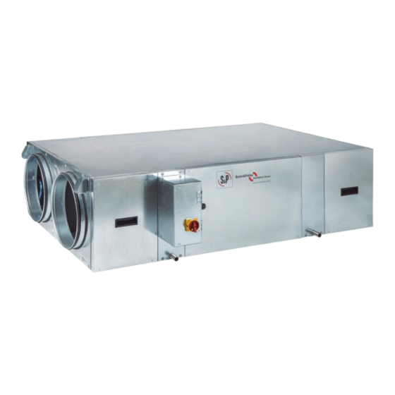
- Page 1 CAD COMPACT ECOWATT...
-
Page 2: Table Of Contents
INDEX 1. INTRODUCTION ..................................3 2. SAFETY REGULATIONS AND “CE” MARKING ..........................3 3. GENERAL INSTRUCTIONS .................................3 4. UNIT LABELLING ..................................3 5. HANDLING ....................................4 6. INSTALLATION ..................................4 6.1. INTRODUCTION ...................................4 6.1.1. Outdoor installation ..............................5 6.2. Dimensions and free space for maintenance ........................6 6.2.1. -
Page 3: Introduction
1. INTRODUCTION Thank you for purchasing this appliance. It has been manufactured in full compliance with applicable safety regulations and EU standards. Please read this instruction book carefully, as it contains important information for your safety during the installation, use and maintenance of this product. Keep it at hand for future reference. -
Page 4: Handling
5. HANDLING The CAD-COMPACT ECOWATT units are delivered fixed with screws to the pallets. The handling machines will be adapted to the load and the lifting conditions. In all cases, the lifting will be done at the device’s base. The centre of gravity is located at the centre of the unit. The device must be carefully manipulated only in the horizontal position. -
Page 5: Outdoor Installation
Model Total weight of unit Anti vibration kit support (kg) (Composed of 4 pcs.) CAD COMPACT 500 KIT AM CAD-COMPACT CAD COMPACT 900 KIT AM CAD-COMPACT CAD COMPACT 1300 KIT AM CAD-COMPACT CAD COMPACT 1800 KIT AM CAD-COMPACT CAD COMPACT 2500 KIT AM CAD-COMPACT CAD COMPACT 3200 KIT AM CAD-COMPACT... -
Page 6: Dimensions And Free Space For Maintenance
6.2. DIMENSIONS AND FREE SPACE FOR MAINTENANCE 6.2.1. Dimensions a) CAD-COMPACT 500 to 1800 models TOP VIEW CONFIGURATION RESULT OF SIMPLE BY DEFAULT (FACTORY SUPPLY) MODIFICATION ON SITE FAN ACCESS FAN ACCESS FAN ACCESS FAN ACCESS FILTER FILTER FILTER FILTER... - Page 7 b) CAD-COMPACT 2500 to CAD-COMPACT 4500 models TOP VIEW CONFIGURATION RESULT OF SIMPLE BY DEFAULT (FACTORY SUPPLY) MODIFICATION ON SITE FAN ACCESS FAN ACCESS FAN ACCESS FAN ACCESS FILTER FILTER FILTER FILTER ACCESS ACCESS ACCESS ACCESS ELECTRICAL CABINET OUTDOOR AIR INTAKE SUPPLY NEW AIR EXTRACT INDOOR AIR EXHAUST INDOOR AIR...
-
Page 8: Free Space For Maintenance
TOP VIEW TOP VIEW CONFIGURATION RESULT OF SIMPLE MODIFICATION ON SITE BY DEFAULT (FACTORY SUPPLY) Model Unit Filters Heat exchanger Fans CAD-COMPACT 500 1120 500* / 550** CAD-COMPACT 900 1345 500* / 680** CAD-COMPACT 1300 1495 1218 500* / 1020**... -
Page 9: Range Specifications
Maximum Maximum Weight connections airflow heat recovery power supply absorbed current** (kg) 150Pa** unit* power** (mm) (kW) CAD-COMPACT 500 82,2 1/230V, 50-60Hz 0,31 CAD-COMPACT 900 82,0 1/230V, 50-60Hz 0,45 CAD-COMPACT 1300 1.120 82,3 1/230V, 50-60Hz 0,88 CAD-COMPACT 1800 1.670 82,7... -
Page 10: Electrical Connection
6.6. ELECTRICAL CONNECTION The CAD-COMPACT ECOWATT range are supplied without a complete operating control integrated in the unit. The elec- trical components included in the unit (fans, by-pass servomotor, filter pressure switches and temperature probes) are supplied wired in an electrical cabinet located in one side of the unit. To access the electrical terminal block and conveniently make the electrical connection of the accessories it is advisable to remove the connection board, follow the following sequence: 1. -
Page 11: Fan Operation Without Speed Regulation. Operation At Maximum Speed
Control wiring The wiring will depend on the needs of each installation as well as the accessories used for it. The following image shows the functions and identifications of the existing electrical connectors inside the electrical cabinet: GREEN / VERDE GREEN / VERDE WHITE / BLANCO WHITE / BLANCO RED / ROJO RED / ROJO... -
Page 12: Vav Control (Variable Airflow), Manual Adjustment
6.6.3.1. VAV control (Variable airflow), manual adjustment It is possible to control in VAV mode manually with an external potentiometer. Manual control by external poten- tiometer REB-ECOWATT (accessory). 6.6.3.1.1. Manual adjustment by REB-ECOWATT (accessory) Simultaneous control of the supply and extract fans Supply fan REB-ECOWATT BLUE... -
Page 13: Cav Control (Constant Airflow)
6.6.3.3. CAV control (constant airflow) The inverter is used to guarantee an specific constant air volume in the duct system, regardless of the filters clogging state. CAD-COMPACT units are equipped with EC motors. The motors have specific terminals for sending a regulation signal to control fan speed (0-10V). -
Page 14: Cop Control (Constant Pressure)
“” and “”. When set, press the “OK” button to memorise the factor k. The actual measured value is displayed. If a airflow range is selected it is not necessary to enter a range of pressures. Model K factor CAD-COMPACT 500 CAD-COMPACT 900 CAD-COMPACT 1300 CAD-COMPACT 1800... -
Page 15: Pressure Switch Connection
Position of the pressure taps of the TDP-D transmitter in COP systems with control of the supply pressure EXTRACTION DUCT OF BUILDING DUCT OF NEW AIR INPUT CONTROL TDP-D AERO-REG (Accessory) (Accessory) 6.6.3.5. Pressure switch connection All CAD-COMPACT range of heat recovery units have differencial pressure switches to perform the control of polluted filters. -
Page 16: Reverse Outdoor Air / Indoor Air Side
Detail of the connection to the CONTROL AERO-REG to enable the control of clogged filters: CONTROL AERO-REG CAD-COMPACT -ECOWATT (Accessory) GREEN / VERDE Extract WHITE / BLANCO Filter (ΔP) GREEN / VERDE Supply WHITE / BLANCO Filter (ΔP) Filter OK: 1-2 Continuous Dirty filter: 1-3 Continuous 6.7. -
Page 17: Inspection, Maintenance And Cleaning
3. Replace the electrical connection label existing in the back side of the electrical terminal box with the one symmetri- cal label supplied in the accessory bag. 4. Only in cold climates where by-pass is used as part of the defrost strategy of the heat exchanger: Reverse the direc- tion of the by-pass so that it remains at the supply of the unit. -
Page 18: Additional Filter Installation
Filters spare parts table Model Accessory filters and spare parts for CAD-COMPACT* CAD COMPACT 500 AFR-CAD COMPACT 500 G4 AFR-CAD COMPACT 500 M5 AFR-CAD COMPACT 500 F7 AFR-CAD COMPACT 500 F9 CAD COMPACT 900 AFR-CAD COMPACT 900 G4 AFR-CAD COMPACT 900 M5 AFR-CAD COMPACT 900 F7 AFR-CAD COMPACT 900 F9 CAD COMPACT 1300 AFR-CAD COMPACT 1300 G4 AFR-CAD COMPACT 1300 M5 AFR-CAD COMPACT 1300 F7 AFR-CAD COMPACT 1300 F9... -
Page 19: Condensation Drainpipe
7.5. CONDENSATION DRAINPIPE Inspect the drainpipe regularly and make sure it is not blocked, if this is the case, remove the obstruction. Check that the drain pipe was done according to the indication included in the point CONNECTIONS of this manual. The siphon should always be full of water. - Page 20 S&P SISTEMAS DE VENTILACIÓN, S.L.U. C. Llevant, 4 Polígono Industrial Llevant 08150 Parets del Vallès Barcelona - España Tel. +34 93 571 93 00 www.solerpalau.com Ref. 9023119000...
Need help?
Do you have a question about the CAD-COMPACT 500 and is the answer not in the manual?
Questions and answers