BUSCH COBRA NC 0600 C Instruction Manual
Dry screw vacuum pumps
Hide thumbs
Also See for COBRA NC 0600 C:
- Instruction manual (48 pages) ,
- Instruction manual (40 pages)

Related Manuals for BUSCH COBRA NC 0600 C


Summary of Contents for BUSCH COBRA NC 0600 C
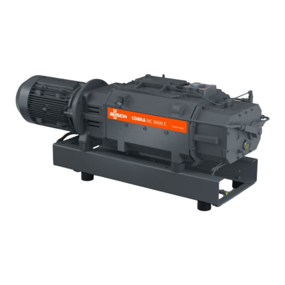
- Page 1 COBRA Dry Screw Vacuum Pumps NC 0600 C, NC 0630 C Water-Cooled Version (WCV) Instruction Manual 0870567092 | A0007_en-US | Original instructions 4/14/2023...
-
Page 2: Table Of Contents
Table of Contents Table of Contents Safety ..................................Product Description ............................. Operating Principle ............................. Intended Use ............................... Start Controls............................... Standard Features............................... 2.4.1 Water Cooling ............................2.4.2 Temperature Switch ..........................2.4.3 Thermometer ............................2.4.4 Sealing Systems ............................ Optional Accessories............................2.5.1 Inlet Filter .............................. 2.5.2 Gas Ballast Valve........................... - Page 3 Table of Contents Oil Level Inspection............................. Cooling Liquid Level Inspection ........................Replacing the Gas Ballast Filter (Optional)....................... Oil Change................................Cooling Liquid Change ............................Overhaul ................................Decommissioning ..............................10.1 Dismantling and Disposal ..........................Spare Parts ................................Troubleshooting ..............................Technical Data ..............................Cooling Liquid ...............................
-
Page 4: Safety
Safety Prior to handling the machine, this instruction manual should be read and understood. If anything needs to be clarified, please contact your Busch representative. Read this manual carefully before use and keep for future reference. This instruction manual remains valid as long as the customer does not change anything on the product. -
Page 5: Product Description
Product Description | 2 Product Description Description Suction connection (Inlet) Discharge connection (Outlet) Condensate drain Cooling liquid drain valve Cooling liquid fill plug Cooling liquid pump Cooling liquid vent plug Cooling water inlet Cooling water outlet Eye bolt Gas ballast valve Magnetic plug Motor terminal box Nameplate... -
Page 6: Operating Principle
Conveying of other media leads to an increased thermal and/or mechanical load on the machine and is permissible only after a consultation with Busch. The machine is intended for the placement in a non-potentially explosive environment. The machine is capable of maintaining ultimate pressure, see Technical Data. -
Page 7: Start Controls
Product Description | 2 Start Controls The machine comes without start controls. The control of the machine is to be provided in the course of installation. The machine can be equipped with a variable speed drive (option). Standard Features 2.4.1 Water Cooling The machine is cooled by a cooling liquid circuit in the cylinder cover and cylinder. -
Page 8: Mechanical Seals
2 | Product Description 2.5.5 Mechanical Seals The sealing systems can be equipped with mechanical seals. The following variants are possible: ● Oil lubricated single mechanical seals on the motor side and labyrinth seals on the suction side. ● Oil lubricated single mechanical seals on the motor side and suction side. 2.5.6 Nitrogen Panel The nitrogen panel fitted to the base frame allows the supply of nitrogen to a number of different... -
Page 9: Transport
Transport | 3 Transport WARNING Suspended load. Risk of severe injury! ● Do not walk, stand or work under suspended loads. WARNING Lifting the machine using the motor eye bolt. Risk of severe injury! ● Do not lift the machine using the eye bolt fitted to the motor. Only lift the machine as shown. NOTICE In case the machine is already filled with oil. -
Page 10: Storage
4 | Storage Storage ● Seal all apertures with adhesive tape or reuse provided caps. If the machine is to be stored for more than 3 months: ● Wrap the machine in a corrosion inhibiting film. ● Store the machine indoors, in a dry and dust free environment and if possible, in original pack- aging, preferably at temperatures between 5 ... -
Page 11: Installation
● Make sure that the cooling water complies with the requirements, see Cooling Water Connection [➔ 13]. If the machine is installed at an altitude greater than 1000 meters above sea level: ● Contact your Busch representative, the motor should be derated or the ambient temperature limited. Connecting Lines / Pipes ●... -
Page 12: Suction Connection
– DN100 PN16, EN 1092-1 If the machine is used as part of a vacuum system: ● Busch recommends the installation of an isolation valve in order to prevent the machine from turning backwards. ● Make sure that the connection lines cause no stress on the connections of the machine. There- fore, we recommend installing flexible joints on the suction and discharge connections. -
Page 13: Cooling Water Connection
Installation | 5 ● Make sure that the connection lines cause no stress on the connections of the machine. There- fore, we recommend installing flexible joints on the suction and discharge connections. ● Make sure that the counter pressure (also called “back pressure”) at the discharge connection (OUT) does not exceed the maximum allowable discharge pressure, see Technical Data. -
Page 14: Barrier Gas System Connection (Optional)
5 | Installation NOTE Water hardness unit conversion. 1 mg/l (ppm) = 0.056 °dh (german degree) = 0.07 °e (english degree) = 0.1 °fH (french degree) 5.2.4 Barrier Gas System Connection (Optional) Without nitrogen panel Description Barrier gas connection Flow meter Flow regulator Manometer Pressure regulating valve... - Page 15 Installation | 5 With nitrogen panel FME, FS Description Barrier gas connection Flow meter Flow switch Manometer Solenoid valve Nitrogen panel Pressure regulating valve ● Connect the barrier gas connection (BGC) to the gas supply. Connection size: – G1/4, ISO 228-1 Version with nitrogen panel: ●...
-
Page 16: Dilution Gas System Connection (Optional)
5 | Installation 5.2.5 Dilution Gas System Connection (Optional) FME, FR Description Dilution gas connection Flow meter Flow regulator Manometer Solenoid valve Nitrogen panel Pressure regulating valve ● Connect the dilution gas connection (DGC) to the gas supply. Connection size: –... -
Page 17: Purge Gas System Connection (Optional)
Installation | 5 5.2.6 Purge Gas System Connection (Optional) FME, FR Description Purge gas connection Flow meter Flow regulator Inlet flange Manometer Solenoid valve Nitrogen panel Pressure regulating valve ● Connect the purge gas connection to the gas supply. Connection size: –... -
Page 18: Filling Oil
Use of an inappropriate oil. Risk of premature failure! Loss of efficiency! ● Only use an oil type which has previously been approved and recommended by Busch. For oil type and oil capacity see Technical Data and Oil [➔ 45]. 18 | 48... -
Page 19: Filling Cooling Liquid
If there is no sticker (part no. 0565 568 959) on the machine: ● Order it from your Busch representative. Filling Cooling Liquid For cooling liquid type and cooling liquid capacity see Technical Data and Cooling Liquid [➔ 44]. -
Page 20: Liquid Flushing Device Installation (Optional)
5 | Installation Liquid Flushing Device Installation (Optional) Description Flushing liquid fill plug Flushing liquid vessel Flow regulator Inlet flange Level indicator Level switch Solenoid valve ● Electrically connect the solenoid valve (MV), see Wiring Diagram Solenoid Valve [➔ 26]. ● Electrically connect the two level switches (LS), see Wiring Diagram Level Switch [➔ 27]. ●... -
Page 21: Fitting The Coupling
Installation | 5 Fitting the Coupling NOTE Radial screw. For trouble-free operation, use thread locking glue to secure the radial screw. Description Coupling hub (machine side) Coupling spider Coupling hub (motor side) Radial screw / max. admissible torque: 10Nm Machine type Coupling size Value “E”... -
Page 22: Electrical Connection
● Make sure that the motor of the machine will not be affected by electric or electromagnetic dis- turbance from the mains, if necessary seek advice from Busch. ● Make sure that the EMC of the machine is compliant with the requirements of your supply net- work system, if necessary provide further interference suppression (EMC of the machine, see EU Declaration of Conformity [➔ 46] or UK Declaration of Conformity [➔ 47]). - Page 23 ● If the machine is equipped with a power connector, install a residual current protective device to protect persons in case of a defective insulation. ● Busch recommends installing a type B residual protective device suitable for the electrical in- stallation.
-
Page 24: Machine Delivered With A Variable Speed Drive (Option)
● If the machine is equipped with a power connector, install a residual current protective device to protect persons in case of a defective insulation. ● Busch recommends installing a type B residual protective device suitable for the electrical in- stallation. -
Page 25: Wiring Diagram Three-Phase Motor (Pump Drive)
Electrical Connection | 6 Wiring Diagram Three-Phase Motor (Pump Drive) Delta connection (low voltage): Star connection (high voltage): Double star connection, multi-voltage motor with 12 pins (low voltage): Star connection, multi-voltage motor with 12 pins (high voltage): Delta connection, multi-voltage motor with 12 pins (middle voltage): Instruction Manual COBRA NC 0600-0630 C WCV_EN_en 25 | 48... -
Page 26: Wiring Diagram Solenoid Valve (Optional)
Contact: Normally closed Electrical Connection of the Monitoring Devices NOTE In order to prevent potential nuisance alarms, Busch recommends that the control system is configured with a time delay of at least 20 seconds. 26 | 48 Instruction Manual COBRA NC 0600-0630 C WCV_EN_en... -
Page 27: Wiring Diagram Temperature Switch
Electrical Connection | 6 6.5.1 Wiring Diagram Temperature Switch Part no.: 0651 556 533 U = 250 VAC; I = 2.5 A ► cosφ = 1 U = 250 VAC; I = 1.6 A ► cosφ = 0.6 U = 48 VDC; I = 1.25 A Contact: Normally closed Switch point: T = 85 °C... -
Page 28: Commissioning
7 | Commissioning Commissioning CAUTION During operation the surface of the machine may reach temperatures of more than 70°C. Risk of burns! ● Avoid contact with the machine during and directly after operation. CAUTION Noise of running machine. Risk of damage to hearing! If people are present in the vicinity of a machine that is not insulated from noise for extended peri- ods of time: ●... -
Page 29: Conveying Condensable Vapors
Commissioning | 7 ● Make sure that the operating conditions comply with the Technical Data. ● After a few minutes of operation, perform an Oil Level Inspection [➔ 33]. ● After a few minutes of operation, perform a Cooling Liquid Level Inspection [➔ 33]. As soon as the machine is operated under normal operating conditions: ●... -
Page 30: Liquid Flushing Procedure
7 | Commissioning Liquid Flushing Procedure The machine can optionally be equipped with a liquid flushing device. Liquid flushing of the machine is recommended only if the machine is equipped with oil lubricated mechanical seals on both sides. If after the application process a liquid flushing is required: START ●... -
Page 31: Maintenance
Maintenance | 8 Maintenance DANGER Live wires. Risk of electrical shock. ● Electrical installation work must only be executed by qualified personnel. DANGER Maintenance work without disconnecting the variable speed drive. Risk of electrical shock. ● Disconnect and isolate the variable speed drive before attempting any work on it. High voltages are present at the terminals and within the variable speed drive for up to 10 min- utes after disconnection of the electrical supply. -
Page 32: Maintenance Schedule
Risk of injuries! Risk of premature failure and loss of efficiency! ● Maintenance work must only be executed by qualified personnel. ● Respect the maintenance intervals or ask your Busch representative for service. NOTICE Using inappropriate cleaners. Risk of removing safety stickers and protective paint! ●... -
Page 33: Oil Level Inspection
● Change the cooling liquid, see Cooling Liquid Change [➔ 37]. ● Clean the magnetic plugs (MP). Every 16000 hours or after 4 ● Have a major overhaul on the machine (contact Busch). years Oil Level Inspection ● Shut down the machine. -
Page 34: Replacing The Gas Ballast Filter (Optional)
Oil Change NOTICE Use of an inappropriate oil. Risk of premature failure! Loss of efficiency! ● Only use an oil type which has previously been approved and recommended by Busch. 34 | 48 Instruction Manual COBRA NC 0600-0630 C WCV_EN_en... - Page 35 Maintenance | 8 Description Magnetic plug Description Magnetic plug For oil type and oil capacity see Technical Data and Oil [➔ 45]. Instruction Manual COBRA NC 0600-0630 C WCV_EN_en 35 | 48...
- Page 36 __ / __ / ____ Oil type see nameplate Change interval see instruction manual If there is no sticker (part no. 0565 568 959) on the machine: ● Order it from your Busch representative. 36 | 48 Instruction Manual COBRA NC 0600-0630 C WCV_EN_en...
-
Page 37: Cooling Liquid Change
Maintenance | 8 Cooling Liquid Change For cooling liquid type and cooling liquid capacity see Technical Data and Cooling Liquid [➔ 44]. Description Fill up to the top of the vent orifice Instruction Manual COBRA NC 0600-0630 C WCV_EN_en 37 | 48... -
Page 38: Overhaul
● Decontaminate the machine as much as possible and state the contamination status in a ‘Dec- laration of Contamination’. Busch will only accept machines that come with a completely filled in and legally binding signed ‘Declaration of Contamination’ (form downloadable from www.buschvacuum.com). -
Page 39: Decommissioning
Decommissioning | 10 Decommissioning DANGER Live wires. Risk of electrical shock. ● Electrical installation work must only be executed by qualified personnel. CAUTION Hot surface. Risk of burns! ● Before doing anything that requires touching the machine, let it cool down first. ●... -
Page 40: Spare Parts
Risk of premature failure! Loss of efficiency! ● The exclusive use of Busch genuine spare parts and consumables is recommended for the correct functioning of the machine and to validate the warranty. There are no standard spare parts kits available for this product. -
Page 41: Troubleshooting
Busch). Solid foreign matter has en- ● Remove the solid foreign tered the machine. matter or repair the ma- chine (contact Busch). ● Install an inlet filter if neces- sary. A temperature sensor has ● Let the machine cool down. - Page 42 Oil Change [➔ 34]. The machine runs too hot. ● See problem "The machine runs too hot". For resolution of problems not listed in the troubleshooting table, please contact your Busch repre- sentative. 42 | 48 Instruction Manual COBRA NC 0600-0630 C WCV_EN_en...
-
Page 43: Technical Data
Technical Data | 13 Technical Data NC 0600 C NC 0630 C Pumping speed (50Hz / 60Hz) m³/h 600 / 600 630 / 630 Ultimate pressure hPa (mbar) abs. ≤0.01 (without gas ballast) Ultimate pressure hPa (mbar) abs. ≤0.1 (with gas ballast) Nominal motor rating 18.5 / 18.5 15 / 17... -
Page 44: Cooling Liquid
14 | Cooling Liquid Cooling Liquid Zitrec M-25 (ready-to-use) Part number 5 L packaging 0831 563 469 Part number 20 L packaging 0831 238 761 The cooling liquid Zitrec M-25 is ready-to-use and does not require additional water. For further information, consult the website www.arteco-coolants.com. 44 | 48 Instruction Manual COBRA NC 0600-0630 C WCV_EN_en... -
Page 45: Oil
Oil | 15 VSC 100 ISO-VG Oil type Synthetic Part number 1 L packaging 0831 168 356 Part number 5 L packaging 0831 168 357 Part number 10 L packaging 0831 210 162 Part number 20 L packaging 0831 168 359 Instruction Manual COBRA NC 0600-0630 C WCV_EN_en 45 | 48... -
Page 46: Eu Declaration Of Conformity
EU Declaration of Conformity This Declaration of Conformity and the CE-markings affixed to the nameplate are valid for the machine within the Busch scope of delivery. This Decla- ration of Conformity is issued under the sole responsibility of the manufacturer. -
Page 47: Uk Declaration Of Conformity
UK Declaration of Conformity This Declaration of Conformity and the UKCA-markings affixed to the nameplate are valid for the machine within the Busch scope of delivery. This Dec- laration of Conformity is issued under the sole responsibility of the manufacturer. - Page 48 With a network of over 60 companies in more than 40 countries and agencies worldwide, Busch has a global presence. In every country, highly competent local personnel delivers custom-tailored support backed by a global network of expertise. Wherever you are.
Need help?
Do you have a question about the COBRA NC 0600 C and is the answer not in the manual?
Questions and answers