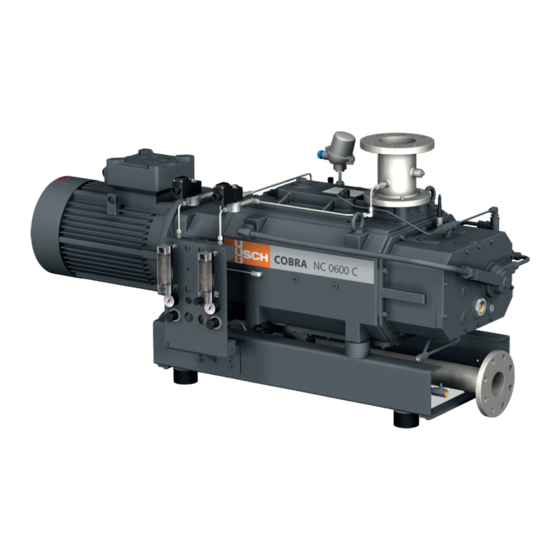
BUSCH COBRA NC 0600 C Instruction Manual
Dry screw vacuum pumps (water-cooled version)
Hide thumbs
Also See for COBRA NC 0600 C:
- Instruction manual (48 pages) ,
- Instruction manual (48 pages)
Table of Contents
Advertisement
Quick Links
Download this manual
See also:
Instruction Manual
Advertisement
Table of Contents

Related Manuals for BUSCH COBRA NC 0600 C


Summary of Contents for BUSCH COBRA NC 0600 C
- Page 1 Instruction Manual COBRA Dry Screw Vacuum Pumps NC 0600 C (water-cooled version) NC 0630 C (water-cooled version) Ateliers Busch S.A. Zone industrielle, 2906 Chevenez Switzerland 0870567092/A0006_en / Original instructions / Modifications reserved 21/03/2019...
-
Page 2: Table Of Contents
Table of Contents Table of Contents 1 Safety........................... 4 2 Product Description ..................... 5 2.1 Operating Principle....................6 2.2 Application ......................6 2.3 Start Controls ....................... 6 2.4 Standard Features....................6 2.4.1 Water Cooling ...................6 2.4.2 Temperature Switch...................7 2.4.3 Thermometer.....................7 2.4.4 Sealing Systems ..................7 2.5 Optional Accessories..................... - Page 3 Table of Contents 7.5 Oil Change ......................28 7.6 Cooling Liquid Change ..................31 8 Overhaul........................32 9 Decommissioning ......................32 9.1 Dismantling and Disposal..................32 10 Spare Parts ........................33 11 Troubleshooting......................33 12 Technical Data ......................36 13 Cooling Liquid ......................36 14 Oil ..........................
-
Page 4: Safety
Safety Prior to handling the machine, this instruction manual should be read and understood. If anything needs to be clarified, please contact your Busch representative. Read this manual carefully before use and keep for future reference. This instruction manual remains valid as long as the customer does not change anything on the product. -
Page 5: Product Description
Product Description | 2 Product Description ODP, MP Condensate drain Cooling liquid drain valve Cooling liquid fill plug Cooling liquid pump Cooling liquid vent plug Cooling water inlet Cooling water outlet Eye bolt Gas ballast valve Suction connection Magnetic plug Motor terminal box Nameplate Oil drain plug... -
Page 6: Operating Principle
Conveying of other media leads to an increased thermal and/or mechanical load on the machine and is permissible only after a consultation with Busch. The machine is intended for the placement in a non-potentially explosive environment. The machine is capable of maintaining ultimate pressure, see Technical Data [► 36]. -
Page 7: Temperature Switch
Product Description | 2 2.4.2 Temperature Switch The temperature switch monitors the oil temperature of the machine. The machine must be stopped when the temperature switch trips (85 °C). 2.4.3 Thermometer The thermometer allows a visual display of the cooling liquid temperature. 2.4.4 Sealing Systems The machine is equipped with labyrinth seals on the motor side and suction side. -
Page 8: Nitrogen Panel
3 | Transport 2.5.6 Nitrogen Panel The nitrogen panel fitted to the base frame allows the supply of nitrogen to a number of different points on the machine. Each device consists of a solenoid valve to open or close the gas circuit, a pressure regu- lator and a flow meter to adjust pressure and volume flow separately. -
Page 9: Storage
Storage | 4 Machine weight: see the technical data or the nameplate (NP) WARNING Lifting the machine using the motor eye bolt. Risk of severe injury! • Do not lift the machine using the eye bolt fitted to the motor. Only lift the machine as previously shown. -
Page 10: Connecting Lines / Pipes
If a purge gas system or a liquid flushing device being installed: – DN100 PN16, EN 1092-1 If the machine is used as part of a vacuum system: • Busch recommends the installation of an isolation valve in order to prevent the machine from turning backwards. 10 / 40... -
Page 11: Discharge Connection
Installation | 5 5.2.2 Discharge Connection Connection size: At the machine discharge connection: – DN100 ISO-K, DIN 28404 At the silencer (SI) discharge connection (two optional versions available): – DN80 PN16 + ANSI/ASME B16.5-3” class 150 lbs – R3 • Make sure that the discharged gas will flow without obstruction. Do not shut off or throttle the discharge line or use it as a pressurised air source. -
Page 12: Barrier Gas System Connection (Optional)
5 | Installation • To reduce the maintenance effort and ensure a long product lifetime we recommend the following cooling water quality: Hardness mg/l (ppm) < 90 Properties Clean & clear PH value 7 … 8 Particle size µm < 200 Chloride mg/l <... - Page 13 Installation | 5 With nitrogen panel FME, FS Barrier gas connection Flow meter Flow switch Manometer Solenoid valve Nitrogen panel Pressure regulating valve • Connect the barrier gas connection (BGC) to the gas supply. Connection size: – G1/4, ISO 228-1 Version with nitrogen panel: •...
-
Page 14: Dilution Gas System Connection (Optional)
5 | Installation 5.2.5 Dilution Gas System Connection (Optional) FME, FR Dilution gas connection Flow meter Flow regulator Manometer Solenoid valve Nitrogen panel Pressure regulating valve • Connect the dilution gas connection (DGC) to the gas supply. Connection size: – G1/4, ISO 228-1 •... -
Page 15: Purge Gas System Connection (Optional)
* standard litre per minute 5.3 Filling Oil NOTICE Use of an inappropriate oil. Risk of premature failure! Loss of efficiency! • Only use an oil type which has previously been approved and recommended by Busch. 0870567092_NC0630C_WCV_A0006_IM_en 15 / 40... - Page 16 5 | Installation For oil type and oil capacity see Technical Data [► 36] and Oil [► 36]. Oil filling at the motor side Check oil level Oil filling at the suction side Check oil level 16 / 40 0870567092_NC0630C_WCV_A0006_IM_en...
-
Page 17: Filling Cooling Liquid
Change interval see instruction manual If there is no sticker (part no. 0565 568 959) on the machine: • Order it from your Busch representative. 5.4 Filling Cooling Liquid For cooling liquid type and cooling liquid capacity see Technical Data [► 36] and Cooling Liquid [► 36]. -
Page 18: Liquid Flushing Device Installation (Optional)
5 | Installation 5.5 Liquid Flushing Device Installation (Optional) Flushing liquid fill plug Flushing liquid vessel Flow regulator Inlet flange Level indicator Level switch Solenoid valve • Electrically connect the solenoid valve (MV), see Wiring Diagram Solenoid Valve [► 21]. • Electrically connect the two level switches (LS), see Wiring Diagram Level Switch [► 22]. -
Page 19: Electrical Connection
• Provide an overload protection according to EN 60204-1 for the motor. • Make sure that the motor of the machine will not be affected by electric or electro- magnetic disturbance from the mains; if necessary seek advice from Busch. • Connect the protective earth conductor. -
Page 20: Wiring Diagram Three-Phase Motor (Pump Drive)
5 | Installation NOTICE Incorrect connection. Risk of damage to the motor! • The wiring diagrams given below are typical. Check the inside of the terminal box for motor connection instructions/diagrams. 5.7.1 Wiring Diagram Three-Phase Motor (Pump Drive) Delta connection (low voltage): Star connection (high voltage): Double star connection, multi-voltage Star connection, multi-voltage motor... -
Page 21: Wiring Diagram Solenoid Valve (Optional)
2 (-) 5.8 Electrical Connection of the Monitoring Devices NOTE In order to prevent potential nuisance alarms, Busch recommends that the control system is configured with a time delay of at least 20 seconds. 5.8.1 Wiring Diagram Temperature Switch Part no.: 0651 556 533 U = 250 VAC ;... -
Page 22: Wiring Diagram Level Switch (Optional)
5 | Installation 5.8.3 Wiring Diagram Level Switch (Optional) Part no.: 0652 556 531 Connector: M12x1, 4-pin < 6 mW at I < 1 mA; < 38 mW at I = 3.5 mA Switching element function: 1 = Brown ; 4 = Black NAMUR Contact: Normally closed Switch point:... -
Page 23: Commissioning
Commissioning | 6 Commissioning NOTICE The machine can be shipped without oil. Operation without oil will ruin the machine in short time! • Prior to commissioning, the machine must be filled with oil, see Filling Oil [► 15]. NOTICE The machine can be shipped without cooling liquid. Operation without cooling liquid will ruin the machine in short time! •... -
Page 24: Conveying Condensable Vapours
6 | Commissioning As soon as the machine is operated under normal operating conditions: • Measure the motor current and record it as reference for future maintenance and troubleshooting work. 6.1 Conveying Condensable Vapours The machine, equipped either with a gas ballast valve or a dilution gas system, is suitable for the conveyance of condensable vapours within the gas flow. -
Page 25: Gas Purging Procedure
Risk of injuries! Risk of premature failure and loss of efficiency! • Respect the maintenance intervals or ask your Busch representative for service. • Shut down the machine and lock against inadvertent start up. • Turn off the water supply. -
Page 26: Maintenance Schedule
• Check the cooling liquid level, see Cooling Liquid Level Inspection [► 27]. • Check the machine for oil leaks - in case of leaks have the machine repaired (contact Busch). Yearly • Carry out a visual inspection and clean the machine from dust and dirt. -
Page 27: Cooling Liquid Level Inspection
• Shut down the machine. • Let the machine cool down. • Fill up if necessary, see Filling Cooling Liquid [► 17]. 7.4 Replacing the Gas Ballast Filter (Optional) Busch genuine spare parts Gas ballast filter: part no. 0562 550 434 Discard the part 0870567092_NC0630C_WCV_A0006_IM_en... -
Page 28: Oil Change
NOTICE Use of an inappropriate oil. Risk of premature failure! Loss of efficiency! • Only use an oil type which has previously been approved and recommended by Busch. Oil draining at the motor side Magnetic plug Cleaning cloth Drain pan... - Page 29 Maintenance | 7 Oil draining at the suction side Magnetic plug Cleaning cloth Drain pan For oil type and oil capacity see Technical Data [► 36] and Oil [► 36]. Oil filling at the motor side Check oil level 0870567092_NC0630C_WCV_A0006_IM_en 29 / 40...
- Page 30 Last oil change __ / __ / ____ Oil type see nameplate Change interval see instruction manual If there is no sticker (part no. 0565 568 959) on the machine: • Order it from your Busch representative. 30 / 40 0870567092_NC0630C_WCV_A0006_IM_en...
-
Page 31: Cooling Liquid Change
Maintenance | 7 7.6 Cooling Liquid Change For cooling liquid type and cooling liquid capacity see Technical Data [► 36] and Cooling Liquid [► 36]. Fill up to the top of the vent orifice 0870567092_NC0630C_WCV_A0006_IM_en 31 / 40... -
Page 32: Overhaul
• Decontaminate the machine as much as possible and state the contamination status in a ‘Declaration of Contamination’. Busch will only accept machines that come with a completely filled in and legally binding signed ‘Declaration of Contamination’. (Form downloadable from www.buschvacuum.com) Decommissioning •... -
Page 33: Spare Parts
• The exclusive use of Busch genuine spare parts and consumables is recommended for the correct functioning of the machine and to validate the warranty. There is no standard spare parts kits available for this product, if you require Busch gen- uine parts: •... - Page 34 Busch). Solid foreign matter has • Remove the solid foreign entered the machine. matter or repair the ma- chine (contact Busch). • Install an inlet filter if ne- cessary. A temperature sensor has • Let the machine cool reached the switch point.
- Page 35 Oil Change [► 28]. The machine runs too hot. • See problem "The ma- chine runs too hot". For the solution of problems not mentioned in the troubleshooting chart contact your Busch representative. 0870567092_NC0630C_WCV_A0006_IM_en 35 / 40...
-
Page 36: Technical Data
12 | Technical Data 12 Technical Data NC 0600 C NC 0630 C Pumping speed m³/h 600 / 600 630 / 630 (50Hz / 60Hz) Ultimate pressure (without gas ballast) hPa (mbar) abs. ≤0.01 Ultimate pressure (with gas ballast) hPa (mbar) abs. ≤0.1 Nominal motor rating 18.5 / 18.5 15 / 17... -
Page 37: Eu Declaration Of Conformity
This Declaration of Conformity and the CE-mark affixed to the nameplate are valid for the machine within the Busch scope of delivery. This Declaration of Conformity is issued under the sole responsibility of the manufacturer. When this machine is integrated into a superordinate machinery the manufacturer of the superordinate machinery (this can be the operating company, too) must conduct the conformity assessment process for the superordinate machine or plant, issue the Declaration of Conformity for it and affix the CE-mark. - Page 38 Note...
- Page 39 Note...
- Page 40 Colombia Korea South Africa www.buschvacuum.com/co www.buschvacuum.com/kr www.buschvacuum.com/za info@buschvacuum.co busch@busch.co.kr info@busch.co.za Czech Republic Malaysia Spain www.buschvacuum.com/cz www.busch.com.my www.buschvacuum.com/es info@buschvacuum.cz busch@busch.com.my contacto@buschiberica.es Denmark Mexico Sweden www.buschvacuum.com/dk www.buschvacuum.com/mx www.buschvacuum.com/se info@busch.dk info@busch.com.mx info@busch.se www.buschvacuum.com 0870567092/A0006_en / © Ateliers Busch S.A.
Need help?
Do you have a question about the COBRA NC 0600 C and is the answer not in the manual?
Questions and answers