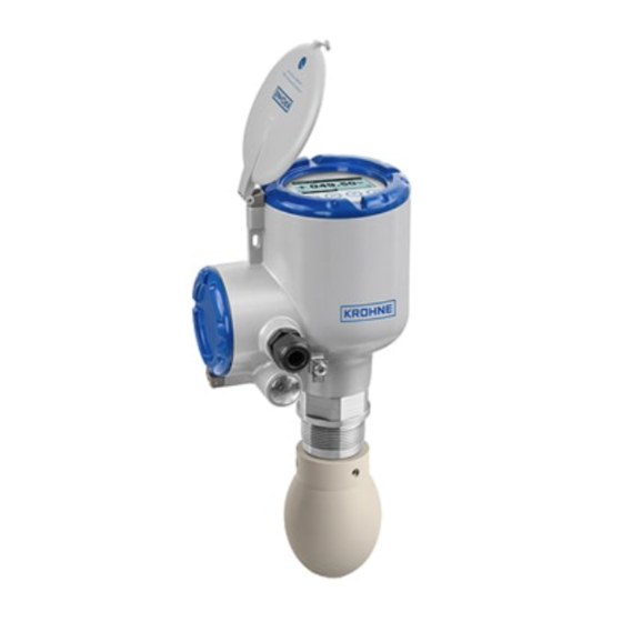
Sign In
Upload
Manuals
Brands
KROHNE Manuals
Measuring Instruments
OPTIWAVE 5400 C
KROHNE OPTIWAVE 5400 C Manuals
Manuals and User Guides for KROHNE OPTIWAVE 5400 C. We have
5
KROHNE OPTIWAVE 5400 C manuals available for free PDF download: Handbook, Supplementary Instructions Manual
KROHNE OPTIWAVE 5400 C Handbook (180 pages)
24 GHz Radar (FMCW) Level Transmitter for liquids in basic process applications
Brand:
KROHNE
| Category:
Transmitter
| Size: 6.59 MB
Table of Contents
Table of Contents
3
Safety Instructions
7
Software History
7
Intended Use
8
Certification
8
Radio Approvals
9
European Union (EU)
9
And Canada
12
Safety Instructions from the Manufacturer
15
Copyright and Data Protection
15
Disclaimer
15
Product Liability and Warranty
16
Information Concerning the Documentation
16
Warnings and Symbols Used
17
Safety Instructions for the Operator
17
Device Description
18
Scope of Delivery
18
Device Description
19
Visual Check
20
Nameplates
21
Nameplate (Examples)
21
Installation
22
General Notes on Installation
22
Storage
22
Transport
23
Pre-Installation Requirements
23
Pressure and Temperature Ranges
24
Recommended Mounting Position
25
General Notes
25
Tanks with Dish-Shaped and Conical Bottoms
27
Mounting Restrictions
28
General Notes
28
Process Connections
30
LPR Devices: Recommendations for Pits and Tanks Made of Non-Conductive Materials
36
Standpipes (Stilling Wells and Bypass Chambers)
37
How to Attach Antenna Extensions
41
How to Turn or Remove the Display Module (Option)
44
Weather Protection
45
How to Attach the Weather Protection to the Device
45
How to Open the Weather Protection
47
Electrical Connections
48
Safety Instructions
48
General Notes
48
Electrical Installation: Output Options with Cable Gland
49
Electrical Installation: Output Options with an M12 Male Connector
53
Electrical Connection for Current Output
53
Non-Ex Devices
53
Devices for Hazardous Locations
54
Ingress Protection
54
Networks
55
General Information
55
Point-To-Point Connection
55
Multi-Drop Networks
56
Start-Up
57
Start-Up Checklist
57
How to Start the Device
57
Operating Concept
57
Digital Display Screen
58
Display Screen Layout
58
Keypad Buttons
59
Remote Communication with Pactware
61
Remote Communication with the AMS™ Device Manager
62
Operation
63
User Modes
63
Normal Mode
63
Program Mode
67
General Notes
67
Protection of the Device Settings (Access Levels)
68
How to Get Access to the Quick Setup Menu
70
Keypad Functions
71
How to Save Settings Changed in Program Mode
74
Menu Overview
75
Function Description
81
Further Information on Device Configuration in Program Mode
101
Standard Setup
101
Empty Spectrum Recording
104
HART® Network Configuration
106
Distance Measurement
107
Level Measurement
109
How to Configure the Device to Measure Volume or Mass
111
How to Measure Correctly in Tanks with Curved or Conical Bottoms
113
How to Make a Filter to Remove Radar Signal Interference
114
Status Messages and Diagnostic Data
115
Service
122
Periodic Maintenance
122
General Notes
122
Maintenance of the O-Rings for the Housing Covers
122
How to Clean the Top Surface of the Device
123
How to Clean Horn Antennas under Process Conditions
123
Service Warranty
124
Spare Parts Availability
124
Availability of Services
124
Returning the Device to the Manufacturer
125
General Information
125
Form (for Copying) to Accompany a Returned Device
126
Disposal
127
Disassembly and Recycling
128
General Notes
128
Compact Version (C)
128
Technical Data
133
Measuring Principle
133
Technical Data
135
Measuring Accuracy
142
Minimum Power Supply Voltage
143
Guidelines for Maximum Operating Pressure
144
Dimensions and Weights
146
Description of HART Interface
159
General Description
159
Software History
160
Connection Variants
160
Point-To-Point Connection - Analogue / Digital Mode
160
Multi-Drop Connection (2-Wire Connection)
161
HART® Device Variables
161
Field Communicator 475 (FC 475)
161
Installation
161
Operation
162
Asset Management Solutions (AMS)
162
Installation
162
Parameter for the Basic Configuration
162
Field Device Tool / Device Type Manager (FDT / DTM)
163
Installation
163
Operation
163
Process Device Manager (PDM)
163
HART® Menu Tree for AMS
164
Overview AMS Menu Tree (Positions in Menu Tree)
164
AMS Menu Tree (Details for Settings)
165
HART® Menu Tree for PDM
168
Overview PDM Menu Tree (Positions in Menu Tree)
168
PDM Menu Tree (Details for Settings)
169
Appendix
172
Accessories: General Items
172
Accessories: Process Connection Kits for the Level Transmitter
173
Glossary
174
Advertisement
KROHNE OPTIWAVE 5400 C Supplementary Instructions Manual (36 pages)
Brand:
KROHNE
| Category:
Transmitter
| Size: 0.8 MB
Table of Contents
Table of Contents
2
1 Introduction
4
Scope of the Document
4
Revision History
4
Type Code for Devices that Can Operate in SIL Mode
5
Device Description
6
Related Documentation
7
Terms and Definitions
7
2 Specification of the Safety Function
9
Preconditions
9
Definition of the Safety Function
9
General Notes
9
Current Output
10
Fault Response Time
11
Safety Application Conditions (SAC)
12
General
12
Installation
12
Electrical Connection
13
Functionally-Safe Configuration
13
Operation Modes
14
SIL Mode
14
Non-SIL Mode
14
Maintenance Mode
14
3 Operation
15
Operation in SIL Mode
15
General Notes
15
Device Configuration for Operation in SIL Mode
15
How to Change the Configuration of a Device Operated in SIL Mode
18
General Notes
18
How to Change Device Operation from SIL Mode to Non-SIL Mode
18
Error Conditions
19
Parameter Types
21
Safety-Critical Parameters
21
Safety-Relevant Parameters
21
Non-SIL Parameters
22
Limits for Parameters Related to Tank Configuration
22
Homogeneous Redundancy
23
How to Set up a System with Homogeneous Redundancy
23
How to Estimate the Effect of Common Cause Failures
24
4 Service
25
Maintenance
25
Availability of Services
25
How to Check Measurement Accuracy before Operation in SIL Mode
25
General Notes
25
Measurement Accuracy Check (in Process Conditions)
25
Operation Modes and Proof Tests
26
How to Reset the Fail-Safe Flags
29
Troubleshooting
29
5 Technical Data
30
Characteristics for the Device Safety Function
30
Useful Lifetime of Electronic Components
30
Assumptions
31
Measuring Accuracy
32
Support for SIL-Approved Devices
32
KROHNE OPTIWAVE 5400 C Supplementary Instructions Manual (36 pages)
Brand:
KROHNE
| Category:
Measuring Instruments
| Size: 1.09 MB
Table of Contents
Table of Contents
2
1 General Safety Information
4
Scope of the Document
4
Device Description
4
Standards and Approvals
5
Equipment Protection Levels (EPL)
5
Ex Ia-Approved Devices
5
Ex Db Ia- and Ex Ia Tb-Approved Devices
7
Ex IC Devices
9
Iecex Nameplate
11
2 Installation
12
Special Conditions
12
Precautions
12
General Notes
12
Electrostatic Discharge
13
Optional Purging System
14
Optional Heating/Cooling System
16
Operating Conditions
17
Ambient and Process Connection Temperatures
17
3 Electrical Connections
21
General Notes
21
Terminal Compartment
22
How to Open the Terminal Compartment
22
How to Close the Terminal Compartment
23
Terminal Tightening Capacity
24
Equipotential Bonding System
24
Ex Ia and Ex IC Equipment
25
How to Connect the Electrical Cables
25
Maximum Intrinsically-Safe Values for the Electrical Circuit
25
Supply Voltage
25
Ex Db Ia / Ex Ia Tb Equipment
26
General Notes
26
How to Connect the Electrical Cables
26
Supply Voltage
27
4 Start-Up
28
5 Service
29
Periodic Maintenance
29
Keep the Device Clean
29
How to Remove the Device
30
OPTIWAVE 6300: Replacement of the Signal Converter
30
OPTIWAVE 7300: Replacement of the Signal Converter
31
Manufacturer
31
Advertisement
KROHNE OPTIWAVE 5400 C Supplementary Instructions Manual (32 pages)
Brand:
KROHNE
| Category:
Transmitter
| Size: 1.74 MB
Table of Contents
Table of Contents
2
1 General Safety Information
4
Scope of the Document
4
Device Description
4
Standards and Approvals
4
Equipment Protection Levels (EPL) and Dust Zones
5
Ex Ia-Approved Devices
5
Ex D Ia- and Ex Iad Td-Approved Devices
7
NEPSI Nameplates
9
2 Installation
10
Special Conditions
10
Precautions
10
General Notes
10
Electrostatic Discharge
11
Optional Purging System
12
Optional Heating/Cooling System
13
Operating Conditions
14
Ambient and Process Connection Temperatures
14
3 Electrical Connections
18
General Notes
18
Terminal Compartment
18
How to Open the Terminal Compartment
18
How to Close the Terminal Compartment
19
Terminal Tightening Capacity
19
Equipotential Bonding System
20
Ex Ia and Ex Iad Equipment
20
How to Connect the Electrical Cables
20
Maximum Intrinsically-Safe Values for the Electrical Circuit
21
Supply Voltage
21
Electrical Schematic
21
Ex D Ia / Ex Iad Td Equipment
22
General Notes
22
How to Connect the Electrical Cables
22
Supply Voltage
23
Electrical Schematic
24
4 Start-Up
25
5 Service
26
Periodic Maintenance
26
Keep the Device Clean
26
How to Remove the Device
27
OPTIWAVE 6300: Replacement of the Signal Converter
27
OPTIWAVE 7300: Replacement of the Signal Converter
28
Manufacturer
28
Returning the Device to the Manufacturer
29
General Information
29
Form (for Copying) to Accompany a Returned Device
30
KROHNE OPTIWAVE 5400 C Supplementary Instructions Manual (32 pages)
Brand:
KROHNE
| Category:
Measuring Instruments
| Size: 1.21 MB
Table of Contents
Table of Contents
2
1 General Safety Information
4
Scope of the Document
4
Device Description
4
Standards and Approvals
4
Equipment Protection Levels (EPL) and Dust Zones
5
Ex Ia-Approved Devices
5
Ex D Ia- and Ex Iad Td-Approved Devices
7
Nameplate
9
2 Installation
10
Special Conditions
10
Precautions
10
General Notes
10
Electrostatic Discharge
10
Optional Purging System
12
Optional Heating/Cooling System
13
Ambient and Process Connection Temperatures
14
3 Electrical Connections
18
General Notes
18
Terminal Compartment
18
How to Open the Terminal Compartment
18
How to Close the Terminal Compartment
19
Terminal Tightening Capacity
20
Equipotential Bonding System
20
Ex Ia and Ex Iad Equipment
21
How to Connect the Electrical Cables
21
Maximum Intrinsically Safe Values for the Electrical Circuit
21
Supply Voltage
21
Ex D Ia / Ex Iad Td Equipment
22
General Notes
22
How to Connect the Electrical Cables
22
Supply Voltage
23
Maximum Voltage for the Electrical Circuit
24
4 Start-Up
25
5 Service
26
Periodic Maintenance
26
Repairs
26
Keep the Device Clean
26
How to Remove the Device
26
OPTIWAVE 6300: Replacement of the Signal Converter
27
OPTIWAVE 7300: Replacement of the Signal Converter
27
Manufacturer
28
Advertisement
Related Products
KROHNE OPTIWAVE 5200 C
KROHNE OPTIWAVE 5200 F
KROHNE OPTISWITCH 5250C
Krohne OPTIWAVE 5200 C/F
KROHNE BATCHFLUX 5500 C
KROHNE BATCHFLUX 5015 K Series
KROHNE UFS 500 F/5STR-EEx
KROHNE OPTIGAS 5010C
KROHNE OPTIFLUX 5000 F
KROHNE OPTISWIRL 5080
KROHNE Categories
Measuring Instruments
Transmitter
Accessories
Switch
Media Converter
More KROHNE Manuals
Login
Sign In
OR
Sign in with Facebook
Sign in with Google
Upload manual
Upload from disk
Upload from URL