Makita LH1040F Instruction Manual
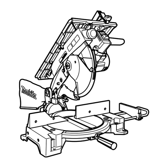
Table top miter saw
Hide thumbs
Also See for LH1040F:
- Instruction manual (152 pages) ,
- Original instruction manual (112 pages) ,
- Technical information (20 pages)

Subscribe to Our Youtube Channel
Related Manuals for Makita LH1040F


Summary of Contents for Makita LH1040F
- Page 1 INSTRUCTION MANUAL Table Top Miter Saw LH1040 LH1040F 015234 DOUBLE INSULATION IMPORTANT: Read Before Using.
-
Page 2: Specifications
ENGLISH (Original instructions) SPECIFICATIONS Model LH1040 / LH1040F Blade diameter 255 mm - 260 mm Blade body thickness 1.6 mm - 1.8 mm Riving knife thickness 2.0 mm Hole diameter For all countries other than European countries 25.4 mm and 25 mm... -
Page 3: General Power Tool Safety Warnings
000331 Sound power level (L ) : 107 dB (A) Yasushi Fukaya Uncertainty (K) : 3 dB (A) Director Makita, Jan-Baptist Vinkstraat 2, 3070, Belgium Wear ear protection GEA005-3 ENG900-1 General Power Tool Safety Vibration The vibration total value (tri-axial vector sum) determined... - Page 4 When operating a power tool outdoors, use an 20. Disconnect the plug from the power source extension cord suitable for outdoor use. Use of and/or the battery pack from the power tool a cord suitable for outdoor use reduces the risk of before making any adjustments, changing electric shock.
- Page 5 Use only saw blades specified by the 23. Knock out any loose knots from workpiece manufacturer and which conform to EN847-1. BEFORE beginning to cut. The groove width of the cut must be thicker 24. Do not use the tool in the presence of than the riving knife and the blade body must flammable liquids or gases.
-
Page 6: Installation
− Injury or damage caused by loose tool misaligned saw blade. KICKBACK causes the attachments which unexpectedly ejection of the workpiece from the tool back slide out/from the power tool due to towards the operator. KICKBACKS CAN LEAD sudden damage, wear improper SERIOUS... -
Page 7: Functional Description
Always install the auxiliary plate using the notch in the FUNCTIONAL DESCRIPTION tool's base and secure it by tightening the hex bolt before operation. CAUTION: For European countries Always be sure that the tool is switched off and • Installing the holders unplugged before adjusting or checking function on the tool. - Page 8 If any of these blade guards becomes discolored With the tool unplugged, rotate the blade by hand while through age or UV light exposure, contact a Makita holding the handle all the way down to be sure that the service center for a new guard. DO NOT DEFEAT OR blade does not contact any part of the lower base.
-
Page 9: Switch Action
Always be sure that the tool is switched off and • For Model LH1040F only unplugged before installing or removing the blade. Use only the Makita socket wrench provided to • 1. Lamps install or remove the blade. Failure to do so may result in overtightening or insufficient tightening of the hex bolt. - Page 10 1. Stopper pin 1. Saw blade 2. Blade guard B 012646 005546 To remove the blade, first loosen the clamping screw so that the lower blade guard B is lowered as shown in the figure. 1. Blade case 2. Arrow 3.
-
Page 11: Adjusting Riving Knife
You could suffer serious personal injury while using the tool without a properly aligned riving knife. If they are not aligned for any reasons, always have Makita authorized service center repair it. Don't remove the riving knife. •... - Page 12 NOTE: 1. Rip fence To change the rip fence pattern, remove the rip • 2. Rip fence holder fence from the rip fence holder by loosening the 3. Two screws clamping screw (A) and change the facing of the rip fence to the rip fence holder so that the rip fence faces the rip fence holder according to your work as shown in the figure.
- Page 13 WARNING: 1. Dust bag Never use your hand to hold the workpiece that • 2. Fastener requires your hand to be any closer than 100 mm from the blade area. In this case, always use the optional vise to secure the workpiece. After any cutting operation, raise the blade gently.
-
Page 14: Operation
before turning again gently clockwise. Vertical vise (optional accessory) The maximum width of the workpiece which can be secured by the horizontal vise is 130 mm. 1. Vise rod 2. Screw Holders and holder assembly 3. Vise knob (optional accessories) 4. - Page 15 wait until the blade attains full speed. Then gently lower CAUTION: the handle to the fully lowered position while applying Do not apply excessive pressure on the handle • pressure in parallel with the blade. When the cut is when cutting. Too much force may result in completed, switch off the tool and WAIT UNTIL THE overload of the motor and/or decreased cutting BLADE HAS COME TO A COMPLETE STOP before...
- Page 16 workpiece. Then secure the set plate with the screw. CAUTION: When the set plate is not used, loosen the screw Never attempt to cut thick or round aluminum • and turn the set plate out of the way. extrusions. Thick aluminum extrusions may come loose during operation and round aluminum NOTE: extrusions cannot be secured firmly with this tool.
-
Page 17: Work Helpers
Always secure the rip fence firmly, or dangerous Remove the rip fence, clamping screw (A), flat washer • kickbacks may occur. and square nut from the rip fence holder and then attach Always use "work helpers" such as push sticks and and secure the auxiliary fence to the rip fence holder by •... -
Page 18: Adjusting The Cutting Angle
Adjusting the cutting angle 1. Auxiliary fence This tool is carefully adjusted and aligned at the factory, 2. Push block but rough handling may have affected the alignment. If your tool is not aligned properly, perform the following: Miter angle 1. -
Page 19: Replacing Carbon Brushes
To maintain product SAFETY and RELIABILITY, repairs, any other maintenance or adjustment should be performed by Makita Authorized Service Centers, always using Makita replacement parts. 005575 Adjust the 45° bevel angle only after performing 0°... -
Page 20: Optional Accessories
Only use accessory or attachment for its stated purpose. If you need any assistance for more details regarding these accessories, ask your local Makita Service Center. Steel & Carbide-tipped saw blades • Auxiliary plate • Vise assembly (Horizontal vise) •... - Page 24 Makita Jan-Baptist Vinkstraat 2, 3070, Belgium Makita Corporation Anjo, Aichi, Japan www.makita.com 884548I224...
Need help?
Do you have a question about the LH1040F and is the answer not in the manual?
Questions and answers