Advertisement
Quick Links
Advertisement

Related Manuals for Broyhill SCREEN HOUSE GAZEBO 10 L X 12 W TPGAZ24109


Summary of Contents for Broyhill SCREEN HOUSE GAZEBO 10 L X 12 W TPGAZ24109
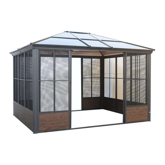
- Page 1 TPGAZ24109 810613813 SCREEN HOUSE GAZEBO...
-
Page 3: Parts List
PARTS LIST Label Description Part Image Upper center connector Lower center connector Short left crossbar Short right crossbar Long left crossbar Long right crossbar Front & rear regular frame Side regular frame Sliding door Sliding door... - Page 4 PARTS LIST Label Description Part Image Crossbar inner connector Post Base plate Sliding door bottom rail Sliding door upper rail Frame corner connector Door frame support tube Corner protector Stopper Short support bar Long support bar connector...
- Page 5 PARTS LIST Label Description Part Image Left roof joint Right roof joint Mid roof joint Upper reinforcement strip Upper reinforcement strip Upper reinforcement strip Bottom reinforcement strip Bottom reinforcement strip Bottom reinforcement strip Left Edge Right Edge Mid Edge...
- Page 6 PARTS LIST Label Description Part Image Short support bar cap Long support bar cap connector connector Left upper panel Left upper panel Right upper panel Right upper panel Mid panel...
-
Page 7: Hardware List
HARDWARE LIST Label Description Part Image M6 x 15 mm Bolt M6 x 15 mm Bolt M6 x 35 mm Bolt Regular frame plug M6 x 15 mm Bolt M4 x 16 mm Bolt Pipe Plug Bolt Cover M6 x 15 mm Bolt Washer M6... - Page 8 HARDWARE LIST Label Description Part Image Wrench-4# Wrench-5# Wrench-4# Wrench Stake Washer M5...
-
Page 9: Helpful Hints
HELPFUL HINTS • Tools needed and not included • Separating parts before starting Provided in hardware pack How many people needed for the installation work... - Page 10 STEP 1 1.Fix the Base plate (G1) to the Post (G) with Bolts(AA).
- Page 11 STEP 2 X 16 X 16 X 16 2. Connect the Long left crossbar (C1) and the Long right crossbar (C2) with Bolts (AA ) through the Crossbar inner Connector (F).
- Page 12 STEP 3 X 10 X 10 X 10 3.Attach the Stopper (O2) to the Long crossbar (C1/C2) with Bolts (AA), then attach the Connector (V1) to the Long crossbar (C1/C2) with Bolts (AA)
- Page 13 STEP 4 X 16 X 16 X 16 4. Connect the Short left crossbar (B1) and Short right crossbar (B2) with Bolts (AA) via the Crossbar inner connector (F), connect the Connector (V1) to the cross member at the same time.
- Page 14 STEP 5 5.Attach the Stopper (O2) to the Short crossbar (B1/B2) with bolts (AA).
- Page 15 STEP 6 X 16 X 16 X 16 X 16 6.1 Connect the assembled Short crossbar (B1/B2) and Long crossbar (C1/C2) to the Post (G) with bolts (AA/BB/MM/GG). Note: No need Cap (SS) on outside. 6.2 Attach the Corner protector (O1) to the Crossbar (B1/B2/C1/C2) with Bolts (AA).
- Page 16 STEP 7 X 24 X 40 X 16 X 24 7.1Attach the middle hole of he Frame corner connector. 7.2 Connect the upper ends of the regular frame ( D1/D2) to the crossbar (C1/C2/B1/B2) with Bolts (CC ), then connect the holes on both sides of the Frame corner connector (J) to the regular frame (D1/D2) with Bolts (AA) individually.
- Page 17 STEP 8 X 16 X 16 X 20 B1 B2 8.1 Secure the upper ends of the Side regular frame(D1) to the Crossbar (B1/B2) with Bolt (CC) and Washer (LL). 8.2 Connect the Regular frames(D2) together with Connector (N) by using the Bolts (AA).
- Page 18 STEP 9 9.Connect the Door rame support tube (K) between the Front & rear regular frame (D1) and (D1) with the Bolt (FF). Tips: Be sure ±5mm of tolerance when installation here completes.
- Page 19 STEP 10 X 16 X 16 10.Connect the Sliding door bottom rail (H) with Bolts (CC) and Washer M6 (LL) by means of Front & rear regular frame (D1) and Door frame support tube.
- Page 20 STEP 11 11. Insert the Sliding door upper rail (I) into the top connector of the Sliding door (E1/E2).
- Page 21 STEP 12 X 16 12. Secure the Rail cap (HH) to both ends of the Sliding door upper rail with Bolts (EE).
- Page 22 STEP 13 X 16 X 16...
- Page 23 STEP 13 OPEN Note: Pull down the door handle , then the Sliding door (E2) will be open “OUTSIDE VIEW ” 13. Insert the lower end of the Sliding door into the Sliding door bottom rail (H) , then stand the door up and attach the upper end to the Long crossbar (C1/C2) with Bolts (AA) and fasten the Caps (MM) Note: If the two doors cannot be pushed or pulled smoothly or are not aligned up and down after...
- Page 24 STEP 14 X 20 X 20 X 20 14.Insert the Bolts (JJ) into the Lower center connector (A2) from the topend , then screw on the Nuts (KK) by inserting the bottom end. Note: Do not tighten Washer M6 (LL) at the the nut, just screw it halfway to the Bolt.
- Page 25 STEP 15 X 16 15.1 Attach the Connector (V2) to the Long support bar (M) with Bolts (AA). 15.2 Insert the two Bolts (JJ),Washer M6(LL) nuts (KK) into the grooves of the Long support bar (M) as shown in the figure.
- Page 26 STEP 16 X 12 X 12 16. Insert the two bolts (JJ) Washer M6 (LL) Wrench-5# (OO) into the grooves of the Short support bar (L) as shown in the figure.
- Page 27 STEP 17 Note: Adjust the Lower center connector (A2) as shown in the figure to parallel with the Long crossbar (C1/C2) 17. Insert the Bolts (JJ) in the Lower center connector (A2) into the Long support bar (M) as well as the Connector (V2),tighten the Bolts (JJ), attach the Connector (V2) located under the Long support bar (M) to the Post (G) with the Bolts (AA), and fasten the Caps (MM).
- Page 28 STEP 18 18. Insert the Rail cap (HH) of the Lower center connector (A2) into the Short support bar (L), tighten the Rail cap (HH), attach the bottom side of the Short support bar (L) to the Connector (V1) with the Bolts (AA), and fasten the Caps (MM). Adjust the 6 support bars to make sure they are all in proper position, making sure they are perpendicular and parallel.
- Page 29 STEP 19 X 20 19.1 Secure the Upper center connector(A1) to the Lower center connector (A2) by the Bolts (AA). 19.2 Cover the Bolt cover (II) onto the Bolts under the Lower Center Connector.
- Page 30 STEP 20 20. Slide the panel (①③⑤) through the slot of the Support bar (L/M) and adjust the position of the (left/right) upper panel①③⑤.
- Page 31 STEP 21 21. Insert the Roof joint (P1/P2/P3) into the lower slot of the support bar (L/M). Adjust the position to make sure they are vertically parallel. Repeat for each side.
- Page 32 STEP 22 22.Insert the Panel (②④⑤) into the slot of the Support bar. Adjust the position of the (left/right) lower panel (②④⑤). Repeat for each side.
- Page 33 STEP 23 X 10 X 20 X 10 23.1 Put the Edge (S1/S2/S3) onto the Support bar (L/M) with Bolts (AA) and fasten the Caps (MM). Repeat the above steps for the rest of the Edges and Short Support bars . Adjust the position of the Edges tomake sure they are vertical and parallel.
- Page 34 STEP 24 X 20 24.1 Attach the ends of the Upper reinforcement strip (Q1/Q2/Q3) to the Long support bar (M) and Short support bar (L) by fixing them to the Bolts (JJ) shown in steps 14 to 16. 24.2 Attach the ends of the Bottom reinforcement strip (R1/R2/R3) to the Long support bar (M) and Short support bar (L), by fixing them to the Bolts (JJ) shown in steps14 to 16.
- Page 35 STEP 25 25.Thread the Stakes (RR) through the Base plate (G1) into the ground to secure the gazebo..
Need help?
Do you have a question about the SCREEN HOUSE GAZEBO 10 L X 12 W TPGAZ24109 and is the answer not in the manual?
Questions and answers
Hi there. Is it possible to install on the door on the side of the Gazebo, rather than on the front ?