Table of Contents

Related Manuals for Ecoflam MULTIFLAM 500.1 PRE


Summary of Contents for Ecoflam MULTIFLAM 500.1 PRE
- Page 1 GAS/HEAVY OIL BURNERS MULTIFLAM 500.1 PRE MULTIFLAM 600.1 PRE Technical data Operating instructions Electric diagrams Spare parts list Gas train manual is separate MULTIFLAM 600.1 PRE TL LMV51 S 3146127 18-06-2018...
- Page 2 Servomotor SQM48 - Air damper motor pre-setting Adjusting the intermediate burner capacity Pressure switch adjustment Maintenance program Troubleshooting instructions Operating troubles Appendix Control box - Damper actuators Fluidics nozzle chart Bergonzo nozzle tables Pump and pressure regulators Electrical diagrams Spare parts list 420010940500 www.ecoflamburners.com...
-
Page 3: General Warnings Conformity Declaration
GENERAL WARNINGS CONFORMITY DECLARATION Important notes Declaration of conformity Use the accessories provided Ecoflam burners have been designed and for dual fuel burners (flange, gasket, pins and nuts) to built in compliance with all current install the burner onto the boiler, regulations and directives. -
Page 4: Burner Designation
For burners over 1700 kW gas train connection pipe must be ordered. Kits and accessories are managed and delivered separately. Component type BBCH Burner Body with Combustion Head (without gas train) GTCP Gas Train Connection pipe Gas Train (delivered separately) 420010940500 www.ecoflamburners.com... -
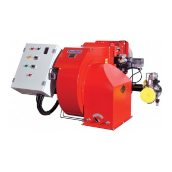
Page 5: Burner Description
GEFRAN SAOG I 0 II Heavy oil lamp POS 0: STOP POS 1: NAFTA POS 2: GAS Selector (GAS / 0 / HEAVY OIL) SARA Auxiliaries Resistances switch Gas lamp POS 0: OFF POS 1: ON Reset button 420010940500 www.ecoflamburners.com... - Page 6 Gas governor / Filter Tightness control Modulation Kit Max Pressure switch Other accessories FGDR - FILTER KITTC- Model KITMD-RWF50 KITPRES50 Compulsory EN676 Compulsory > 1200 kW Probe-... KITPRES150 420010940500 www.ecoflamburners.com...
-
Page 7: Technical Data
1,1 kW Nozzles Type according to the output requested Fuel thermo regulator Type GEFRAN Electrical pre-heater GAS CATEGORY BY COUNTRY Gas category Country BE CH CZ DE DK ES FR GB GR HU NO PL 2R3R 2H3B/P CY MT 420010940500 www.ecoflamburners.com... - Page 8 12000 13000 1000 2000 3000 4000 5000 6000 7000 8000 9000 10000 11000 14000 15000 16000 17000 adapt it to some special boiler Nm 3 /h 1000 1100 1200 1300 1400 1500 1600 1700 or application. 420010940500 www.ecoflamburners.com...
-
Page 9: Overall Dimensions
OVERALL DIMENSIONS D - D1 SUNTEC D = Short head D1= Long head Dimensions (mm) Model MULTIFLAM 500.1 PRE 1470 1297 MULTIFLAM 600.1 PRE 1470 1297 Burnerboiler mounting flange Fixing hole dimensions are “I” and “L” as per dimension table. -
Page 10: Oil Operating Mode General Safety Functions
Any failure of the flame signal at the end of A voltage failure will result in a regular the safety period and a flame signal during shut-off of the burner. Upon voltage 420010940500 www.ecoflamburners.com... - Page 11 155: pilot gas train 176: oil pump 178: solenoid valve 180: nozzle rod 184: output control valve 311: return oil pressure switch 313: min gas pressure switch CV: check valve RL: return line VL: suction line VLO: working oil valve 420010940500 www.ecoflamburners.com...
-
Page 12: Installation
(see figures). The setting of the mixing and ignition unit according to the boiler output will be performed during commissioning procedure. 4. Check that the head is preset at 50%. 420010940500 www.ecoflamburners.com... - Page 13 Ecoflam heavy oil and dual fuel heavy oil ACCESSORIES burners do have in the electrical panel the fuel Service tanks + Pumps units.
- Page 14 3. Bleed and pressure gauge port 4. Vacuum gauge port 5. Pressure adjustment 6. Nozzle outlet 7. Heater 8. Hose 9. Oil filter 10. Oil ball valve WARNING: Check that the pump rotation is correct and before start up it has been pre-filled 420010940500 www.ecoflamburners.com...
- Page 15 10 - Oil ring control pressure device 11 - Heating cable 12 - Main heavy oil storage tank 13 - Heating coil Hot water water Return section hot water pipe oil pipe oil pipe heating cable insulation hot water pipe 420010940500 www.ecoflamburners.com...
- Page 16 TWO PIPE Return INSTALLATION NOZZLE SELECTION Please refer to diagram to select Ecoflam recommended nozzle for the output that is required given the output necessary in the installation. Regular maintenance is highly recommended. Intake from Tank Nozzle has to be cleaned in petrol or paraffin and if filter or other parts are...
- Page 17 GAS VALVES AND INSTRUMENTS boiler furnaces the result of the leak test (furnace) and allow the boiler door to be GROUP must be duly certified. swivelled out if required. The gas valves and instruments group can 420010940500 www.ecoflamburners.com...
- Page 18 WARNING: Note that the head loss diagram is only indicative and does vary Multiflam 500.1 depending on the setting of the head. OUTPUT - Stm3/h 420010940500 www.ecoflamburners.com...
- Page 19 VGD 40.080 VGD 40.100 + F- DN100 VGD 40.100 VGD 40.125 + F- DN125 VGD 40.125 flow m LEGENDA Pf: Back pressure of furnace Pb: Pressure of burner (combustion head + complete gas train) Pin: Minimum inlet pressure 420010940500 www.ecoflamburners.com...
- Page 20 VGD 40.080 VGD 40.100 + F- DN100 VGD 40.100 VGD 40.100 + F- DN125 VGD 40.125 flow m LEGENDA Pf: Back pressure of furnace Pb: Pressure of burner (combustion head + complete gas train) Pin: Minimum inlet pressure 420010940500 www.ecoflamburners.com...
- Page 21 3 kW. STC: boiler thermostat the mains supply connection. For more information, please contact the STS: safety thermostat Ecoflam staff. SA: active probe ELECTRICAL CONNECTION SP: passive probe 1) of the burner - Built-in electrical cabinet Use cable gland in order to secure the required level of protection.
- Page 22 Type gas Type oil Gas calorific value Oil calorific value Gas inlet pressure mbar Adjustment gas pressure Volumetric gas flow rate Burner output Burner output Flue gas temperature C° Air temperature C° Performance Corrective action Operator name Company 420010940500 www.ecoflamburners.com...
-
Page 23: Exhaust Gas Test
- and CO 2500 for heavy oil S (CO max = 15,60%) 2000 1500 = 21 CO max - CO gem = % 1000 gem = % CO measured on dry flue gases Fan capacity reduced by [%] 420010940500 www.ecoflamburners.com... - Page 24 The optimal position depends on the output that we need to reach but the default setting shall be modified only when you are not able to reach the suggested combustion value by adjusting the air flow in the maximum flame. 420010940500 www.ecoflamburners.com...
- Page 25 10 seconds until the regulator automatically goes out from “configuration level”. ADJUSTMENT OF FUEL THERMOSTATS Inside the electrical panel there is a safety termostat that is set up at 160°C. Said adjustments can be slightly modified following the type of fuel and particular uses. 420010940500 www.ecoflamburners.com...
- Page 26 Do never allow the pump working without oil for more than three minutes. NOTE: before starting the burner, check that the return pipe is open. An eventual obstruction could damage the pump sealing device. 420010940500 www.ecoflamburners.com...
- Page 27 – pressure switch tap. LEGENDA 176: oil pump 178: solenoid valve 180: nozzle rod 184: output control valve 185: manometer 186: pressure regulator 311: return oil pressure switch CV: check valve RL: return line VL: suction line VLO: working oil valve 420010940500 www.ecoflamburners.com...
- Page 28 Servomotor SQM48 Air damper motor presetting Air adjustment is accomplished through LMV parameters setting. Refer to LMV manual attacched. 420010940500 www.ecoflamburners.com...
- Page 29 The maximum gas pressure switch has the function to check that the gas pressure after the gas train and before the head does not exceed the pre-set limits. Max gas pressure switch: it is available as a kit for different pressure. 420010940500 www.ecoflamburners.com...
-
Page 30: Maintenance Program
The exhaust gas loss can be calculated as follows: as follows: = exhaust gas temperature [°C] = combustion air temperature [°C] 0,37 0,49 = volumetric content of carbon = (195-22)( + 0,009) = 7,48% = (195-22)( + 0,007) = 7,83% dioxide [%] 10,8 12,8 420010940500 www.ecoflamburners.com... - Page 31 GAS FILTER CLEANING GAS PILOT FILTER CLEANING ATTENTION: Periodically clean oil cartridge with gasoline and the gas filter cartridge with air and replace them if it is necessary! Check and clean the gas filter in the pilot gas valve 420010940500 www.ecoflamburners.com...
-
Page 32: Troubleshooting Instructions
2. Availability of electric power in the operation and in faulty and interlocked the start-up and operating program. burner system. position. APPENDIX Control box Damper actuators Refer to LMV and SQM 45/48..manual attacched. 420010940500 www.ecoflamburners.com... - Page 33 APPENDIX Fluidics nozzle chart 420010940500 www.ecoflamburners.com...
- Page 34 APPENDIX Fluidics nozzle chart 420010940500 www.ecoflamburners.com...
- Page 35 APPENDIX Fluidics nozzle chart 420010940500 www.ecoflamburners.com...
- Page 36 APPENDIX Bergonzo nozzle tables 420010940500 www.ecoflamburners.com...
- Page 37 APPENDIX Bergonzo nozzle tables 420010940500 www.ecoflamburners.com...
- Page 38 APPENDIX Bergonzo nozzle tables 420010940500 www.ecoflamburners.com...
- Page 39 : 5 bars max. heavy oil : 5 bars max. Rated speed 3600 rpm max. Starting torque 0,3 N.m Choice of heater Cartridge Ø 12 mm Fitting according to DIN 40430, NFC 68190 (N°9 elec.) Rating 80-100 W 420010940500 www.ecoflamburners.com...
- Page 40 APPENDIX Electrical diagrams 420010940500 www.ecoflamburners.com...
- Page 41 APPENDIX Electrical diagrams 420010940500 www.ecoflamburners.com...
- Page 42 APPENDIX Electrical diagrams 420010940500 www.ecoflamburners.com...
- Page 43 420010940500 www.ecoflamburners.com...
- Page 44 APPENDIX Spare parts 420010940500 www.ecoflamburners.com...
- Page 45 APPENDIX Spare parts list MULTIFLAM 500.1 PRE MULTIFLAM 600.1 PRE N° DESCRIPTION code code AIR PRESSURE SWITCH DUNGS LGW10 A2P 65323047 65323047 PRESSURE GAUGE 65321341 65321341 AIR INTAKE SET 65322346 65322346 WIELAND PLUG 6 pin 65322072 65322072 4 pin 65322064 65322064...
- Page 46 APPENDIX Spare parts list MULTIFLAM 500.1 PRE MULTIFLAM 600.1 PRE N° DESCRIPTION code code HEATING ELEMENT 30 W 65324207 65324207 OIL PUMP SUNTEC TA4C40106 65322994 65322994 COUPLING 65325386 65325386 HOSES TN 25X1500 C/T 65323181 65323181 OIL FILTER 70501/03 65324103 65324103 PUMP MOTOR 1500 W...
- Page 47 420010940500 www.ecoflamburners.com...
- Page 48 Ecoflam Bruciatori S.p.A. reserves the right to make any adjustments, without prior notice, which is considered necessary or useful to its products, without affecting their main features Ecoflam Bruciatori S.p.A. si riserva il diritto di apportare ai prodotti le modifiche che riterrà necessarie o utili, senza pregiudicarne le caratteristiche principali.
Need help?
Do you have a question about the MULTIFLAM 500.1 PRE and is the answer not in the manual?
Questions and answers