Table of Contents

Related Manuals for Weber mt CR 7 CCD


Summary of Contents for Weber mt CR 7 CCD
- Page 1 OPERATING AND MAINTENANCE INSTRUCTIONS CR 7 CCD Lombardini 15 LD 440 Weber Maschinentechnik GmbH P. O. Box 21 53, D-57329 Bad Laasphe-Rückershausen Phone ++27 54 / 398-0 Telefax (++ 27 54) 3 98-101 (Switchboard) & 3 98-102 (Spare Parts)
- Page 2 CR7CCD...
-
Page 3: Preface
Preface These operating and maintenance instructions describe the safe operation of the CR7 CCD soil compactor. Please read this operation manual and familiarize yourself with all details of your soil compactor before operating the machine for the first time. Carefully follow all instructions and always carry out the described operations in the indicated order. Please refer to the following page for the General Safety Instructions. -
Page 4: General Safety Instructions
General Safety Instructions General All safety notes (see also explanations of the pictogram meanings in the preface) must be read and observed (any lack of clarity must be dispelled before the soil compactor is put into operation), because otherwise the use of the machine may * constitute a risk to life and limb of the user * impair the machine and other valuable property. -
Page 5: Table Of Contents
Table of Contents Preface ..................................3 General Safety Instructions ........................... 4 Technical Description ............................6 Illustration ................................6 Machine Description .............................. 7 1.2.1 Description of the COMPATROL ........................... 8 1.2.2 Principles of Operation ............................8 Specifications ............................... 10 Operation ................................12 Safety Precautions for the Operation ......................... -
Page 6: Technical Description
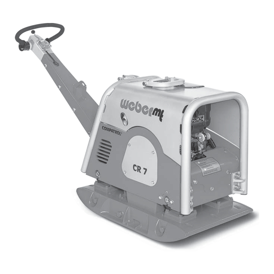
Technical Description 1.1 Illustration Figure 1 Overall View CR 7 CCD 1 Engine 8 Engine bracket 2 Drive lever 9 Vibrator 3 Handle 10 V-belt guard 4 Lifting lug 11 Spring bar (not shown) 5 Ignition lock (not shown) 12 Engine speed adjusting lever... -
Page 7: Machine Description
1.2 Machine Description The CR 7 CCD soil compactors are machines of the walk-behind type used for compaction work in road construction and landscape applications. Propulsion The CR 7 soil compactor is driven by a Lombardini Diesel engine. Important! Please refer to paragraph 1.3 (Specifications) for the performance details of the engine and the whole machine. -
Page 8: Description Of The Compatrol
1.2.1 Description of the COMPATROL Compaction Control System COMPATROL is a continuous compaction control system for soil compactors of the walk-behind-type. The system can be used on soils of the “V1” class (well compactable soils). The COMPATROL compaction control system consists of an acceleration sensor (2/2) fitted to the base plate (2/1) and of the Compaction Control Display (CCD) (3/2) integrated in the dashboard (3/1). - Page 9 When the operating frequency is achieved, the green LED (6/ 1) and at least one of the yellow LEDs (6/2) will light up to indicate that the COMPATROL system is ready for work. Figure 6 During the compaction process, the compaction achieved is continuously measured and optically indicated by the yellow LEDs 1 to 7 (7/8/1).
-
Page 10: Specifications
1.3 Specifications CR 7 CCD Weight Operating weight according to CECE in kg Dimensions Overall length (in mm) 1835 1835 Width with extension plates (in mm) Height with handle folded down (in mm) 1135 1135 Base plate length (contact area in mm) - Page 11 CR 7 CCD Noise and Vibration Data* Sound pressure level LPA (at the operator's place, according to 2000/14/EG, in dB(A)) Sound power level LWA (according to 2000/14/EG, in dB(A)) Hand/arm vibration (weighted root mean square acceleration, 5,2 * at the handle, determined according to 2002/44/EG, Part 1, 3,7 ** in m/s²...
-
Page 12: Operation
2 Operation 2.1 Safety Precautions for the Operation Safety and protection devices Before every shift, the operator must check the operativeness of all controls and safety elements as well as the proper installation of all protection devices. The soil compactor is only allowed to be operated with all protection devices in place. -
Page 13: Transport
2.2 Transport Short distances on the job site can be covered by the soil compactor in accordance with paragraph 2.6. For long distances, however, the compactor can be lifted on an appropriate transport vehicle (truck, trailer) by means of a crane. -
Page 14: Pre-Start Work
2.4 Pre-Start Work Check to ensure that all safety devices are in place. Check the whole soil compactor for evident damage (visual check). Check all screwed connections for tight seat, retighten them if necessary. Check the fuel level, if necessary, add fuel (refer to paragraph 2.4.1). Check the engine oil level, if necessary add engine oil (refer to paragraph 2.4.2). -
Page 15: Checking The Engine Oil Level
2.4.2 Checking the Engine Oil Level Caution! The engine oil level must be checked with the soil compactor standing horizontally on the ground. Pull out the oil dipstick (16/1), wipe it off with a clean, non- fluffing cloth and insert it again. max. -
Page 16: Fitting The Damper Plate
2.4.3 Fitting the Damper Plate - Put the soil compactor out of operation as described in paragraph 2.7. - Lift the soil compactor by means of a crane as described in paragraph 2.2.1. - Put the damper plate beneath the machine. Caution! Do not enter the zone under the suspended load. -
Page 17: Starting
2.5 Starting Danger! Before starting the machine, always ensure that nobody is in the danger area of the soil compactor and that all protective devices are properly in place. When starting the soil compactor in closed premises, always ensure a proper ventilation - danger of poisoning. Caution! Figure 20 Never use starting aid sprays! - Page 18 When the engine has been started, the LEDs (23/1) will light up until the correct frequency is reached. As soon as the correct vibration frequency is reached, the red light-emitting diode (23/2) will be extinguished. If the red LED (23/2) does not go out, please refer to paragraph 4.2 “Trouble Shooting“.
-
Page 19: Compaction Work
2.6 Compaction Work Put the soil compactor into operation (refer to paragraph 2.5). As soon as the engine reaches its operating temperature: push the engine speed adjusting lever (20/1) into the full speed position. Caution! Compaction work is only allowed at full engine speed, otherwise the centrifugal clutch may slip and cause Figure 24 increased wear. -
Page 20: Putting The Soil Compactor Out Of Operation
2.7 Putting the Soil Compactor Out of Operation Before work breaks and at the end of every day’s shift, the soil compactor must be parked on a stable base which should be as horizontal as possible. Warning! If the soil compactor causes an obstruction when being parked, precautionary measures must be taken in order to make the machine visible. -
Page 21: Maintenance
3 Maintenance 3.1 Safety Precautions for Maintenance Work Checks Dependent upon the operating conditions, soil compactors must be made subject to an expert's check for operational safety as required, but at least once a year. The inspection results must be recorded in writing and kept at least until the next inspection. -
Page 22: Maintenance Survey
3.2 Maintenance Survey Any maintenance work required on the soil compactor must be repeated at regular intervals. The column „Maintenance Point´“ refers to the assembly group on which the work indicated in the column „Maintenance Work“ must be carried out. The column „Remarks“... -
Page 23: Description Of The Maintenance Work
3.3 Description of the Maintenance Work 3.3.1 Changing the Engine Oil Put the soil compactor out of operation as described in paragraph 2.7. Caution! Drain off the engine oil at operating temperature and with the soil compactor in horizontal position only. Figure 30 Put a drain pan under the outlet. -
Page 24: Cleaning The Engine Oil Filter
3.3.1.1 Cleaning the Engine Oil Filter - Put the soil compactor out of operation as described in paragraph 2.7. - Drain the engine oil according to paragraph 3.3.1. - Undo the screws (33/1) and remove the lid (33/2) of the filter body. - Pull the oil filter (34/1) out of the crankcase and replace it by a new oil filter. -
Page 25: Cleaning/Replacing The Air Filter Cartridge
3.3.2 Cleaning/Replacing the Air Filter Cartridge Loosen the fastening screw (36/2) and remove the cover (36/1) from the air filter body. Pull the air filter element (37/1) out of the air filter body(37/2) and blow or knock it clean. Caution! If this procedure does not provide a sufficient cleaning (e. -
Page 26: Replacing The Fuel Filter
3.3.3 Replacing the Fuel Filter - Put the soil compactor out of operation as described in paragraph 2.7. - Undo the clips (37/2), remove the diesel fuel lines (37/1) from the fuel filter (37/3) and completely drain the tank. - Remove the clip (37/4) from the fuel filter (37/3) and replace the used filter by a new one. -
Page 27: Checking The Condition And Tension Of The Vibrator V-Belt
3.3.4 Checking the Condition and Tension of the Vibrator V-Belt Put the soil compactor out of operation as described in paragraph 2.7. Undo the screws (38/1) to remove the V-belt guard (38/2). Check the condition of the V-belt (39/1) (cracks, broken out flanks, wear). -
Page 28: Changing The Vibrator Oil
3.3.6 Changing the Vibrator Oil Put the soil compactor out of operation as described in paragraph 2.7. Caution! Change the oil at operating temperature only. Figure 43 When working on the machine, always protect the soil compactor against slipping out of control. - Risk of injury - Thoroughly clean the oil drain plug (43/1) and the area around it. -
Page 29: Hydraulic Control
3.3.7 Hydraulic Control The switch head (24/2) is filled with hydraulic oil. Switching is effected upon actuation of the switch lever (24/1). A hydraulic line connects the reaction end socket (26/1) and the switch head. Important! In case of switching problems, proceed as follows: Figure 45 Remove the oil filler screw (46/2) of the switch head (46/1). -
Page 30: Consumables And Quantities
3.4 Consumables and Quantities Assembly Group Consumable Quantity Summer Winter CR 7 Quality Engine Engine oil SAE 10 W 40 1,2 l (-10 ~ + 50 °C) API - CD CE-CF-CG or SHPD or CCMC - D4 - D5 - PD2 Diesel 5,0 l Diesel according to DIN 51601-DK... -
Page 31: Malfunctions During Operation
4 Malfunctions During Operation 4.1 General If a malfunction occurs on the soil compactor, proceed as follows: Put the soil compactor out of operation as described in paragraph 2.7. Determine the source of the malfunction (refer to paragraph 4.2 - Trouble Shooting). Repair the failure (refer to paragraph 3 (maintenance work) and paragraph 2 (description of the various controls). -
Page 32: Trouble Shooting
4.2 Trouble Shooting Failure Possible Cause Remedy Remarks Soil compactor does Mistake in operating the unit Perform the starting procedure not start as described # 2.5 Lack of fuel Check the fuel level # 2.4.1 Dirty fuel filter Replace the fuel filter # 3.3.3 Dirty air filter Clean/replace the air filter... -
Page 33: Repair And Replacement Work
4.3 Repair and Replacement Work 4.3.1 Replacing the Battery - Put the soil compactor out of operation as described in paragraph 2.7. - Undo the fastening screws (48/1) and remove the battery cover (48/2). - Disconnect the cable plug (49/3). - Disconnect terminals (49/1). -
Page 34: Preserving The Machine
5 Preserving the Machine If the soil compactor is planned to be put out of operation for an extended period of time (approx. 1 ... 6 months), e. g. during the winter season, it must be stored in a frost-proof and dry room. Before storing the machine, however, the preservation measures described in paragraph 5.1 must be taken. -
Page 35: Addresses, Weber Maschinentechnik Gmbh
6 Addresses, Weber Maschinentechnik GmbH For problems, questions and further information refer to one of the following addresses: in Germany WEBER Maschinentechnik GmbH Telefon + 49 (0) 2754 - 398-0 Postfach 2153 Telefax + 49 (0) 2754 - 398101-switchboard 57329 Bad Laasphe - Rückershausen + 49 (0) 2754 - 398102- spare parts- directlinie E-Mail... - Page 36 > Vibratory Plate Compactors > Vibratory Soil compactors > Vibratory Rollers > Joint Cutters > Internal Vibrators and Converters > Vibrating Motors > Stone Saws > Rotary Trowels > and many others Weber MASCHINENTECHNIK GmbH Im Boden D- 57334 Bad Laasphe - Rückershausen P.
Need help?
Do you have a question about the CR 7 CCD and is the answer not in the manual?
Questions and answers