
Related Manuals for Electrolux Professional Wascator FOM71 CLS


Summary of Contents for Electrolux Professional Wascator FOM71 CLS
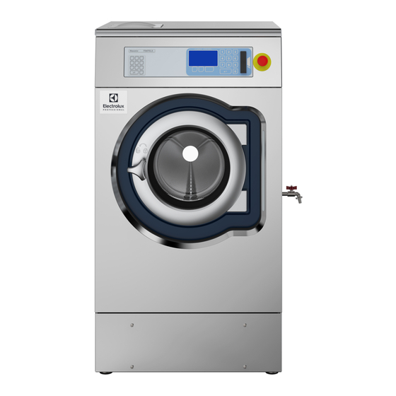
- Page 1 Installation manual Washer extractor Wascator FOM71 CLS 438905451/GB, IE Original instructions 2023.05.22...
-
Page 3: Table Of Contents
Contents Contents 1 Safety Precautions ..........................5 General safety information......................6 Commercial use only........................6 Symbols............................6 Additional notes .........................6 2 Technical data.............................7 Drawing ............................7 Technical data ...........................8 Connections ..........................8 Function/subsystem ........................9 3 Setup ............................... 11 Transportation and unpacking....................11 Siting and floor.........................13 Mechanical installation ......................14 4 Water connection ..........................16 5 Drain connection ..........................17 6 Sample tap ............................17... -
Page 5: Safety Precautions
Installation manual 1 Safety Precautions • Servicing shall be carried out only by authorized personnel. • Only authorized spare parts, accessories and consumables shall be used. • Only use detergent intended for water-wash of textiles. Never use dry cleaning agents. •... -
Page 6: General Safety Information
Read the instructions before using the machine 1.4 Additional notes Note! Weight calibration (only Wascator FOM71 CLS): If the value in the display shows more than ±0.1 kg, reset scale to zero. Level calibration: Check and calibrate if a longer test serie is to commence. -
Page 7: Technical Data
Installation manual 2 Technical data 2.1 Drawing Electrical connection Cold water Hot water Drain Liquid detergent supply Control panel Soap box Door opening, ⌀ 310 mm 1315 1230 1010... -
Page 8: Technical Data
Installation manual 2.2 Technical data Inner drum, volume litres Inner drum, diameter Heating, electricity G-factor Weight, net 2.3 Connections DN20 Water valves connection 3/4″ Recommended water pressure 200–600 Functioning limits for water valve 50-1000 Capacity at 300 kPa l/min Drain valve outer ⌀ 50/75 Draining capacity l/min... -
Page 9: Function/Subsystem
Installation manual 2.4 Function/subsystem Ambient conditions The machine shall be able to function during the same ambient conditions as normal washing ma- chines. However the functional values with toleran- ces will only be valid if following ambient conditions are kept. Voltage Nominal ±2% Frequency... - Page 10 Installation manual Interval switch off temperature – switch on ≤4℃ temperature Soap box Number of compartments Number of programmable liquid detergents Wash programs Memory cards for IEC 60456 ISO 6330 M&S Approvals The machine shall have same approvals as normal washing machines Special equipment Manual tap for sampling of bath water on right side:...
-
Page 11: Setup
Installation manual 3 Setup 3.1 Transportation and unpacking The machine is delivered bolted onto the transport pallet and packed in a crate or box. • Remove packing from the machine. • Remove front and rear foundation panels. Remove the bolts between the machine and pallet. •... - Page 12 Installation manual • Push the machine back and mount the two rear feet and then the two front feet. The feet shall be mounted in the holes on the load sensor bridge. • Lift the machine and remove the transport pallet. •...
-
Page 13: Siting And Floor
Installation manual In order to remove the safety devices: • Remove front and rear panel. • Remove both front metal angels. • Remove both rear metal angels. • The machine may not be moved with the transport securities removed. Save the transport securities for future use. fig.5712 3.2 Siting and floor Install the machine close to a floor drain or open drain. -
Page 14: Mechanical Installation
Installation manual 3.3 Mechanical installation • Mark the site of the machine installation. • The round mark up (A) on the drawing are the site for the feet of the machine. fig.5744A • Two tilt protections shall be mounted for the two feet at the front of the machine. •... - Page 15 Installation manual • Lift the machine in the bottom frame and place it with the feet in the cups. Center the feet in cups as much as possible. • Mount the tilt protection and tighten with two screws. fig.5747A • Check that the machine is placed in level. Adjust with the feet, the lock with the counter nuts. It is of utmost importance that the machine is placed in level, from side to side as well as front to rear.
-
Page 16: Water Connection
Installation manual 4 Water connection All intake connections to the machine are to be fitted with manual shut-off valves and filters, to facilitate installation and servicing. In certain cases non-return valves will need to be fitted before the machine to comply with local plumb- ing regulations. -
Page 17: Drain Connection
Installation manual 5 Drain connection Connect a 75 mm (2 1/2″) flexible rubber hose to the machine’s drain pipe, ensuring a downward flow from the ma- chine. Avoid sharp bends which may prevent proper draining. There shall be an air-gap of 50 mm between the drain hose and the drain. Be sure that the drain hose is flexible enough not causing weight problems for the scale. -
Page 18: Connection Of External Liquid Supplies
Installation manual 7 Connection of external liquid supplies Electrical installation must be carried out by an authorized personnel! All optional equipment connected must be EMC-approved to EN 50081-1 or EN 50082- 2. Distribution card A can be used to control external functions, output and input signals. Only in Japan fig.5331... - Page 19 Installation manual Outputs (200-240V AC): X71:1,2 Signal "Door locked, program on" X72:1 0 V (common) X72:2 Liquid supply 1 X72:3 Liquid supply 2 X72:4 Liquid supply 3 X72:5 Liquid supply 4 X73:1 Detergent box 1 (Y11) X73:2 Detergent box 2 (Y12) X73:3 Detergent box 3 (Y13) X73:4 Detergent box 4 (Y24) X73:5 Detergent box 2 (Y22)
- Page 20 Installation manual If more signals are required the machine can be equipped with a second distribution card B. Outputs (200-240V AC): X75:1 0 V (common) X75:2 Liquid supply 5 X75:3 Liquid supply 6 X75:4 Liquid supply 7 X75:5 Liquid supply 8 X76:1 0 V (common) X76:2 Drain lock X76:3 Drain A...
-
Page 21: Electrical Installation
Installation manual 8 Electrical installation Electrical installation must be carried out by an authorized personnel! Machines with frequency-controlled motors can be incompatible with certain types of earth leakage circuit break- er. It is important to know that the machines are designed to provide a high level of personal safety, which is why items of external equipment such as earth leakage circuit breakers are not necessary. -
Page 22: Electrical Connections
Installation manual 8.1 Electrical connections Heating alternative Voltage alternative Total kW Fuse A Electric heating 200 V 3 AC 220/230 V 1 AC 240 V 1 AC 220 V 3 AC 230/240 V 3 AC 380/400/415 V 3/3N AC... -
Page 23: Function Checks
Installation manual 9 Function checks 9.1 Manual operation • Switch on the machine's main switch. • Check that the drum is empty and close the door. • Close the drain valve. • Open the manual valves for water. In the operating manual, chapter "Manual operation", one can find how to operate the machine manually. •... -
Page 24: Assembling The Ruler
Installation manual 10 Assembling the ruler • Mount the scale and ruler as shown on pictures. fig.X02775... -
Page 25: Calibration Of Level Control System
Installation manual 11 Calibration of level control system The level control system can be individually and manually calibrated. The calibration starts at the level at the bottom of the inner drum. The calibration can be made up to 250 mm from the bottom of the inner drum. A ruler is supplied with the machine where the water level above the inner drum can be read. - Page 26 Installation manual • Close the door. • The ruler has two different scales, one in mm and one in RU units (exactly 2 mm/RU units). fig.X02773 The calibration shall be made in at least five level steps, and the first step when the water just enters the inner drum. More calibration steps can be made if requested.
- Page 27 Installation manual • Press OK • Go down to EXIT • Press SELECT LEVEL CALIBRATION OLD CALIBRATION WILL BE OVERWRITTEN ARE YOU SURE? PRESS OK ELSE PRESS ANY OTHER KEY...
-
Page 28: Calibration Of The Scale (Weight Function)
Installation manual 12 Calibration of the scale (weight function) Zero adjustment of the scale (weight function) The scale itself is calibrated from factory and no adjustment should be necessary unless some scale parts need to be changed. However a zero adjustment needs to be done as the total weight of the machine needs to be pro- grammed into the scale. -
Page 29: Connection Of Thermosensor
Installation manual 13 Connection of thermosensor An external thermosensor can be connected to the machine. On the rear side of the drum is a socket for connecting the sensor. Use a 1/4″ clamping nut for the sensor. Maximum insertion of the sensor is 50 mm from the edge of the socket. Remember that there is a rotating drum. fig.X02776... -
Page 30: Disposal Information
Installation manual 14 Disposal information 14.1 Disposal of appliance at end of life Before disposing of the machine, make sure to carefully check its physical condition, and in particular any parts of the structure that can give or break during scrapping. The machine’s parts must be disposed of in a differentiated way, according to their different characteristics (e.g. - Page 32 Electrolux Professional AB 341 80 Ljungby, Sweden www.electroluxprofessional.com...
Need help?
Do you have a question about the Wascator FOM71 CLS and is the answer not in the manual?
Questions and answers