
Subscribe to Our Youtube Channel
Related Manuals for Electrolux Professional Compass Pro WH6-8


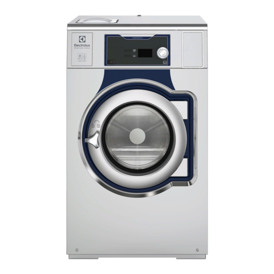
Summary of Contents for Electrolux Professional Compass Pro WH6-8
- Page 1 Installation manual Washer extractor WH6–7, WH6–8, WH6–11, WH6–14, WH6–20, WH6–27, WH6–33 Compass Pro Type W3..438917550/GB, IE Original instructions 2022.11.14...
-
Page 3: Table Of Contents
Contents Contents 1 Safety Precautions ..........................5 General safety information......................6 Commercial use only........................6 Symbols............................6 2 Warranty terms and exclusions......................7 3 Technical data.............................8 Drawing ............................8 3.1.1 WH6–7, WH6–8, WH6–11 ....................8 3.1.2 WH6–14 .........................9 3.1.3 WH6–20, WH6–27, WH6–33 ..................10 Technical data ......................... 11 Connections ..........................12 4 Setup ...............................13 Unpacking ..........................13... -
Page 5: Safety Precautions
Installation manual 1 Safety Precautions • Servicing shall be carried out only by authorized personnel. • Only authorized spare parts, accessories and consumables shall be used. • Only use detergent intended for water-wash of textiles. Never use dry cleaning agents. •... -
Page 6: General Safety Information
Installation manual appliance. Cleaning and user maintenance shall not be made by children without supervision. • Additional requirements for other countries: – This appliance is not intended for use by persons (including children) with reduced physical, sensory or mental capabilities, or lack of experience and knowledge, unless they have been given supervision or instruction concerning use of the appliance by a person responsible for their safety. -
Page 7: Warranty Terms And Exclusions
Warranty will be applicable where the customer has used only genuine spare parts and has performed maintenance in accordance with Electrolux Professional user and maintenance documentation made available in paper or elec- tronic format. Electrolux Professional strongly recommends using Electrolux Professional approved cleaning, rinse and descaling agents to obtain optimal results and maintain product efficiency over time. -
Page 8: Technical Data
Installation manual 3 Technical data 3.1 Drawing 3.1.1 WH6–7, WH6–8, WH6–11 fig.X01718 Operating panel Door opening, WH6–7, WH6–8: ⌀ 310 mm, WH6–11: ⌀ 365 mm Detergent container Cold water Hot water Cold/Hot water or Re-used water with network pressure (option) Re-used water from tank/pump or Liquid detergent supply Drain Liquid detergent supply... -
Page 9: Wh6-14
Installation manual 3.1.2 WH6–14 fig.X01751 Operating panel Door opening, WH6–14: ⌀ 395 mm Detergent container Cold/Hot water (Detergent container) Cold water Hot water Cold/Hot water or Re-used water with network pressure (option) Re-used water from tank/pump or Liquid detergent supply Drain Liquid detergent supply Electrical connection... -
Page 10: Wh6-20, Wh6-27, Wh6-33
Installation manual 3.1.3 WH6–20, WH6–27, WH6–33 fig.X01752 Operating panel Door opening, WH6–20, WH6–27, WH6–33: ⌀ 435 mm Detergent container Cold/Hot water (Detergent container) Cold water Hot water Cold/Hot water or Re-used water with network pressure (option) Re-used water from tank/pump or Liquid detergent supply Drain Liquid detergent supply Electrical connection... -
Page 11: Technical Data
Installation manual 3.2 Technical data WH6–7 WH6–8 WH6–11 WH6–14 WH6–20 WH6–27 WH6–33 Weight, net Drum volume litres Drum diameter Drum speed during wash Drum speed during extraction 1245 1245 1165 1113 1054 1007 1007 G-factor, max. Heating: Electricity Heating: Steam Heating: Hot water Frequency of the dynamic 20.8... -
Page 12: Connections
Installation manual 3.3 Connections WH6–7 WH6–8 WH6–11 WH6–14 WH6–20 WH6–27 WH6–33 Water valves 3/4” 3/4” 3/4” 3/4” 3/4” 3/4” 3/4” Recommended water 200–600 200–600 200–600 200–600 200–600 200–600 200–600 pressure Continuous operating 50–800 50–800 50–800 50–800 50–800 50–800 50–800 pressure Capacity at 300 kPa l/min Drain valve... -
Page 13: Setup
Installation manual 4 Setup 4.1 Unpacking 4.1.1 WH6–7, WH6–8, WH6–11 Remove the front and rear panel. Remove the four transport supports. Save the transport supports if the machine needs to be moved in the future. Note! Once the transport supports have been removed, handle the machine carefully to avoid damage to the sus- pension components. - Page 14 Installation manual Remove the machine from the pallet. Note! When moving the machine, handle it with care. Make sure that the machine does not come down on the floor with either of the rear corners first. The side panel of the machine can be damaged. Place the machine on its final position.
-
Page 15: Wh6-14, Wh6-20, Wh6-27, Wh6-33
Installation manual 4.1.2 WH6–14, WH6–20, WH6–27, WH6–33 Note! Two persons are recommended for the unpacking. Remove the side panels. Remove the front and rear panel. Remove the transport securities. Save the transport securities if the machine needs to be moved in the future. Note! Once the transport securities have been removed, handle the machine carefully to avoid damage to the sus- pension components. - Page 16 Installation manual Remove the machine from the pallet. Note! When moving the machine, handle it with care. Place the machine on its final position. Mount the supporting feet. WH6–14, WH6–20, WH6–27 WH6–33 Remount the panels.
-
Page 17: Recycling Instruction For Packaging
Installation manual 4.2 Recycling instruction for packaging fig.X02395 Fig. Description Code Type Wrapping film LDPE 4 Plastics Corner protection PS 6 Plastics Cardboard packaging PAP 20 Paper Pallet FOR 50 Wood Screw FE 40 Steel FE 40 Steel Plastic bag PET 1 Plastics... -
Page 18: Siting
Installation manual 4.3 Siting Install the machine close to a floor drain or open drain. The machine should be positioned so that there is plenty of room for working, both for the user and service personnel. The figure shows minimum distance to a wall and/or other machines. Failure to respect the prescribed distances will prevent easy access for maintenance and service operations. -
Page 19: Mechanical Installation
Installation manual 4.4 Mechanical installation If the machine is not to be mounted on a base the machine must be fastened to the floor with the enclosed expansion bolts. The table shows the correct position of feet and drilling points. WH6–7-WH6–11: Mark and drill two holes (⌀... -
Page 20: Marine Installation
Installation manual 5 Marine installation The maximum inclination allowed in any direction is 4°. To ensure steadiness of the machine; the machine must be fastened to the floor. -
Page 21: Water Connection
Installation manual 6 Water connection All water intake connections to the machine should be fitted with manual shut-off valves and filters, to facilitate instal- lation and servicing. Water pipes and hoses should be flushed clean before installation. The machine shall be connected with new water hoses. Re-used water hoses must not be used. Hoses are to be of an approved type and grade and comply with IEC 61770. - Page 22 Installation manual Water pressure: Continuous operating pressure: 50–800 kPa (0.5-80 kp/cm Maximum: 1000 kPa (10 kp/cm Recommended: 200–600 kPa (2–6 kp/cm Note! If the water pressure is below the minimum value, the wash result can not be guaranteed for certain program. For WRAS-approved machines;...
-
Page 23: Connection Of External Dosing Systems
Installation manual 7 Connection of external dosing systems 7.1 Connection of the hoses The machine is prepared for connection of external dosing systems or water re-use systems etc. The connections are closed at delivery. Open any of the connections that shall be used by drilling a hole where the hoses shall be connected. -
Page 24: Electrical Connection Of External Dosing System
Installation manual 7.2 Electrical connection of external dosing system The power supply to the external dosing system must never be connected to the machine’s incoming terminal block or to the edge connectors on the I/O-board. 7.2.1 Machine with connectors Connect the external dosing system to connections A and B on the machine. Connect the signal cable to B and the power supply to A. -
Page 25: Machine Without Connectors
Installation manual 7.2.2 Machine without connectors Connect the external dosing system to the I/O board, which is located to the right of the incoming power supply. The I/O board has edge connectors for connecting external dosing systems. Edge connectors on the I/O board can be loosened for connecting cables. fig.6572 11 = N 18 = Program run... -
Page 26: Outputs
Installation manual 7.2.3 Outputs Connect the power supply (e.g. 24V DC) for the external liquid supplies to 9 and 10. If an internal power supply (from the machine) is being used, it can be taken from 1 (N) and connected to 9 and from 2 (L) and connected to 10. Max load on the outputs 0.5 A. -
Page 27: Inputs
Installation manual 7.2.4 Inputs The signal level can be 5-24V DC/AC or 100- 240V AC. For 5-24V, the signal reference is connected to 3 and for 100-240V to 4. Potentials on the inputs cannot be mixed. Note! The I/O board will be damaged if the voltage on connection 3 is too high > 24V. Connection 8 may be connected if the program is to pause, e.g. -
Page 28: Drain Connection
Installation manual 8 Drain connection Connect a 75 mm (50 mm for models WH6–7, WH6–8, WH6–11) pipe or rubber hose to the machine’s drain pipe, en- suring a downward flow from the machine. Avoid sharp bends which may prevent proper draining. fig.5330 Drain pump (for models WH6–7, WH6–8, WH6–11) The drainage pipe should be located over a floor drain, drainage channel or the like. -
Page 29: Electrical Connection
Installation manual 9 Electrical connection 9.1 Electrical installation The electrical installation may only be carried out by qualified personnel. Machines with frequency-controlled motors can be incompatible with certain types of earth leakage circuit break- er. It is important to know that the machines are designed to provide a high level of personal safety, which is why items of external equipment such as earth leakage circuit breakers are not necessary but is recommended. -
Page 30: Electrical Connections
Installation manual 9.2 Electrical connections WH6–7 Electrical connections Heating alternative Main voltage Heating power Total power Recommended fuse Electric heated 220-240V 1/1N~ 50/60 220-240V 1/1N~ 50/60 5.4/7.5 5.7/7.8 25/32 220-240V 3~ 50/60 220-240V 3~ 50/60 5.4/7.5 5.7/7.8 16/25 380-415V 3N/3~ 50/60 380-415V 3N/3~ 50/60... - Page 31 Installation manual WH6–14 Electrical connections Heating alternative Main voltage Heating power Total power Recommended fuse Electric heated 220-240V 1/1N~ 50/60 4.8/13.0 5.2/13.4 25/63 220-240V 3~ 50/60 4.8/13.0 5.2/13.4 16/35 380-415V 3N/3~ 50/60 4.8/13.0 5.2/13.4 10/20 440V 3~ 50/60 13.0 13.4 480V 3~ 13.0 13.4...
-
Page 32: Machine Connection
Installation manual 9.3 Machine connection Connect the earth and other two wires as shown. Single-phase connection Three-phase connection 1NAC L2 L3 3N AC L2 L3 1N/1 3N AC L2/N Single phase machines may be powered either by connection between a phase and neutral or by connecting be- tween two phases. -
Page 33: Machine Connection With Ferrite
Installation manual 9.4 Machine connection with ferrite 9.4.1 WH6–14, WH6–20, WH6–27, WH6–33 To obtain approved level of EMC, it is mandatory to use the ferrite which is enclosed with above listed models. (Note that this is only valid for those models). Before connecting to the machine, the protective earth (PE) wire shall be wrapped around the ferrite. -
Page 34: Functions For I/O-Cards
Installation manual 9.5 Functions for I/O-cards The electrical schematic can be one of the following: 9.5.1 External coin meter/Central payment (2A) The signal received from external coin meters must be a pulse between 300–3000 ms (500 ms is recommended) with a minimum pause of 300 ms (500 ms is recommended) between two pulses. fig.6606A... -
Page 35: Central Payment (2B)
Installation manual 9.5.2 Central payment (2B) To start the machine from a central payment system, the payment system must transmit a start pulse to the machine. The start pulse can be either 230V or 24V. In order to receive a feedback signal once the machine has started, 230V or 24V must be connected to connection 19. -
Page 36: Central Payment (2C)
Installation manual 9.5.3 Central payment (2C) The central payment or booking system shall transmit an active (high) signal to the machine once permission has been granted to start the machine. The signal must remain active (high) until the machine starts. A feedback signal will be present on connection 18 and remain active (high) whilst the machine door is closed but the program has not started. -
Page 37: Outputs For Detergent Signals And Inputs For Pause Signals, "Empty" Signal And Price Reduction (2D)
Installation manual 9.5.4 Outputs for detergent signals and inputs for pause signals, "empty" signal and price reduction (2D) The figure shows standard function addressing for machines with the coin program package. By maintaining an active (high) signal on connection 5 ("Price red"), the price of the program can be reduced. This function has a number of uses, including providing reductions during a specific period of the day. -
Page 38: Central Booking/Payment (2F)
Installation manual 9.5.5 Central booking/payment (2F) The central payment or booking system shall provide an active (high) signal to the machine once permission has been granted to start the machine. The signal must remain active (high) until the machine starts. A feedback signal will be present on connection 18 and remain active (high) whilst the program is running. -
Page 39: Machines With I/O Module Type 3
Installation manual 9.5.6 Machines with I/O module type 3 By maintaining an active (high) signal on connection 3 "Price reduction”, the price of the program can be reduced. This function has a number of uses, including providing reductions during a specific period of the day. Whilst the sig- nal remains active (high), the price of the program is reduced by the percentage entered in the price programming menu. -
Page 40: Converting Heating Elements
Installation manual 9.6 Converting heating elements 9.6.1 WH6–7, WH6–8 and WH6–11 can be converted from 400-415V 3AC to 230-240V 1AC with reduced power Disconnect the power to the machine. Demount the front panel and remove the cover to the heating elements. Remove the blue cables. -
Page 41: Wh6-14 Can Be Converted From 380-415V 3N Ac To 220-240V 1N Ac With Reduced Power
Installation manual 9.6.2 WH6–14 can be converted from 380-415V 3N AC to 220-240V 1N AC with reduced power Disconnect the power to the machine. Demount the cover panel to the electrical connections. Remove the cables that are connected to K21:2 and K22:6. Move the remaining cables from L2 and L3 to L1 or N ac- cording to the figure. -
Page 42: Steam Connection
Installation manual 10 Steam connection Inlet pipes connected to the machine must be equipped with a manual shut-off valve to facilitate installation and serv- icing. The connection hose must be of type ISO/1307- 1983 or equivalent. Connection size at filter: DN 15 (BSP 1/2"). Demount the top panel (A). -
Page 43: At First Power Up
Installation manual 11 At first power up When the installation is complete and the power is connected for the first time you will be forced to make the following settings. When one setting is ready you will automatically enter the next one. •... -
Page 44: Function Check
Installation manual 12 Function check May only be carried out by qualified personnel. A function check must be made when the installation is finished and before the machine can be ready to be used. Open the manual water valves. Start a program. •... -
Page 45: Disposal Information
Installation manual 13 Disposal information 13.1 Disposal of appliance at end of life Before disposing of the machine, make sure to carefully check its physical condition, and in particular any parts of the structure that can give or break during scrapping. The machine’s parts must be disposed of in a differentiated way, according to their different characteristics (e.g. - Page 48 Electrolux Professional AB 341 80 Ljungby, Sweden www.electroluxprofessional.com...
Need help?
Do you have a question about the Compass Pro WH6-8 and is the answer not in the manual?
Questions and answers