Sign In
Upload
Download
Table of Contents
Contents
Add to my manuals
Delete from my manuals
Share
URL of this page:
HTML Link:
Bookmark this page
Add
Manual will be automatically added to "My Manuals"
Print this page
×
Bookmark added
×
Added to my manuals
Manuals
Brands
Miller Manuals
Welding System
MigMatic 220
Owner's manual
Miller MIGMATIC 220 Owner's Manual
Hide thumbs
Also See for MIGMATIC 220
:
Owner's manual
(52 pages)
1
2
Table Of Contents
3
4
5
6
7
8
9
10
11
12
13
14
15
16
17
18
19
20
21
22
23
24
25
26
27
28
29
30
31
32
33
34
35
36
37
38
39
40
41
42
43
44
45
46
47
48
49
50
51
52
53
54
55
56
page
of
56
Go
/
56
Contents
Table of Contents
Troubleshooting
Bookmarks
Table of Contents
Table of Contents
Declaration of Conformity
Section 1 − Safety Precautions - Read before Using
Symbol Usage
Arc Welding Hazards
Additional Symbols for Installation, Operation, and Maintenance
California Proposition 65 Warnings
Principal Safety Standards
EMF Information
Section 2 − Definitions
Additional Safety Symbols and Definitions
Miscellaneous Symbols and Definitions
Section 3 − Specifications
Serial Number and Rating Label Location
Specifications
Environmental Specifications
Duty Cycle and Overheating
Volt-Ampere Curves
Section 4 − Installaton
Selecting a Location
Installing Gas Supply
Installing Wire Spool and Adjusting Hub Tension
Positioning Jumper Links (230/400V 3-Phase Models)
Electrical Service Guide
Connecting Input Power (1-Phase and 3-Phase)
Installing Drive Rolls and Wire Guide
Threading Welding Wire and Adjusting Pressure Roll Tension
Section 5 − Operation
Controls for Migmatic 220/250
Burnback and Spot Weld Timer Controls
Controls for Migmatic 220 DX / 250 DX
Burnback and Spot Weld Timer Controls
Welding Power Source Input Line Voltage Adjustment (DX Models Only)
Welding Power Source Setup Menu (DX Models Only)
Trigger Mode Selection (DX Models Only)
Spool Gun Mode (DX Models Only)
Welding Wire Diameter Selection for Synergic MIG (DX Models Only)
Welding Wire Type Selection for Synergic MIG (DX Models Only)
Gas Selection for Synergic MIG (DX Models Only)
Selecting Manual MIG Welding (DX Models Only)
Selecting Synergic MIG Welding (DX Models Only)
Section 6 − Maintenance &Troubleshooting
Routine Maintenance
Circuit Breaker CB1
Unit Overload
Troubleshooting
Section 7 − Electrical Diagrams
Section 8 − Parts List
Advertisement
Quick Links
1
Connecting Input Power (1-Phase and 3-Phase)
2
Controls for Migmatic 220/250
3
Section 7 − Electrical Diagrams
4
Section 8 − Parts List
Download this manual
Visit our website at
www.MillerWelds.com
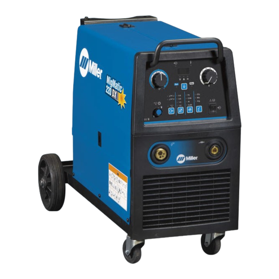
MigMatic 220/250 Base/DX
OWNER'S MANUAL
R
CE
OM-246 691F
2015−06
Processes
MIG (GMAW) Welding
Flux Cored (FCAW) Welding
Description
Arc Welding Power Source
Wire Feeder
File: MIG (GMAW)
Table of
Contents
Previous
Page
Next
Page
1
2
3
4
5
Advertisement
Table of Contents
Troubleshooting
SECTION 6 − MAINTENANCE &TROUBLESHOOTING
34
Troubleshooting
35
Need help?
Do you have a question about the MIGMATIC 220 and is the answer not in the manual?
Ask a question
Questions and answers
Related Manuals for Miller MIGMATIC 220
Welding System Miller MigMatic 220 Owner's Manual
Welder (52 pages)
Tools Miller MigMatic 220DX Owner's Manual
Spool gun (24 pages)
Welding System Miller Thunderbolt 225 Owner's Manual
Cc/ac welding power source for smaw (stick) welding (17 pages)
Welding System Miller Bobcat 225D PLUS Owner's Manual
Engine driven welding generator (52 pages)
Welding System Miller BOBCAT 225 NT Owner's Manual
(74 pages)
Welding System Miller BOBCAT 225G PLUS Owner's Manual
(40 pages)
Welding System Miller HJ134589 Owner's Manual
Miller electric owners manual welding generators hj134589 (44 pages)
Welding System Miller 22A Owner's Manual
(80 pages)
Welding System Miller Multimatic 220 AC/DC Quick Reference
Tig and stick (2 pages)
Welding System Miller Multimatic 220 AC/DC Owner's Manual
(80 pages)
Welding System Miller Spectrum 3080 Owner's Manual
(36 pages)
Welding System Miller Millermatic 252 Owner's Manual
Arc welding power source and wire feeder (56 pages)
Welding System Miller Trailblazer 251 Owner's Manual
Engine driven welding generator (48 pages)
Welding System Miller millermatic 200 SKP-35 Owner's Manual
(79 pages)
Welding System Miller Bobcat 200 Air Pak Owner's Manual
(68 pages)
Welding System Miller Bobcat 265X Owner's Manual
(80 pages)
This manual is also suitable for:
Migmatic 250
Migmatic 250dx
Migmatic 220dx
Table of Contents
Print
Rename the bookmark
Delete bookmark?
Delete from my manuals?
Login
Sign In
OR
Sign in with Facebook
Sign in with Google
Upload manual
Upload from disk
Upload from URL


Need help?
Do you have a question about the MIGMATIC 220 and is the answer not in the manual?
Questions and answers