Table of Contents
Advertisement
Quick Links
CDSW
OM-01932-OB03
November 19, 1996
REV. F 10/18/05
INSTALLATION, OPERATION,
AND MAINTENANCE MANUAL
WITH PARTS LIST
T SERIES PUMP
MODEL
T3A61−B
INCLUDING: /F
THE GORMAN-RUPP COMPANY D MANSFIELD, OHIO
D
GORMAN-RUPP OF CANADA LIMITED
ST. THOMAS, ONTARIO, CANADA
Printed in U.S.A.
www.gormanrupp.com
E
Copyright by the Gorman-Rupp Company
Advertisement
Table of Contents

Related Manuals for GORMAN-RUPP PUMPS T3A61-B


Summary of Contents for GORMAN-RUPP PUMPS T3A61-B
- Page 1 CDSW OM-01932-OB03 November 19, 1996 REV. F 10/18/05 INSTALLATION, OPERATION, AND MAINTENANCE MANUAL WITH PARTS LIST T SERIES PUMP MODEL T3A61−B INCLUDING: /F THE GORMAN-RUPP COMPANY D MANSFIELD, OHIO GORMAN-RUPP OF CANADA LIMITED ST. THOMAS, ONTARIO, CANADA Printed in U.S.A. www.gormanrupp.com Copyright by the Gorman-Rupp Company...
-
Page 2: Table Of Contents
TABLE OF CONTENTS INTRODUCTION ..........PAGE I −... - Page 3 TABLE OF CONTENTS (continued) TROUBLESHOOTING − SECTION D ......PAGE D − 1 PREVENTIVE MAINTENANCE .
-
Page 4: Introduction
T SERIES OM−01932 INTRODUCTION Thank You for purchasing a Gorman-Rupp pump. This pump is a T Series, semi-open impeller, self- Read this manual carefully to learn how to safely priming centrifugal model with a suction check install and operate your pump. Failure to do so valve. -
Page 5: Safety − Section A
T SERIES OM−1932 SAFETY − SECTION A This information applies to T Series ba- ries containing large entrained solids. sic pumps. Gorman-Rupp has no con- Do not attempt to pump volatile, corro- trol over or particular knowledge of the sive or flammable liquids which may power source which will be used. - Page 6 OM−01932 T SERIES of time. If operated against a closed dis- charge valve, pump components will deteriorate, and the liquid could come to a boil, build pressure, and cause the Use lifting and moving equipment in pump casing to rupture or explode. good repair and with adequate capacity to prevent injuries to personnel or dam- age to equipment.
-
Page 7: Installation − Section Bpage B
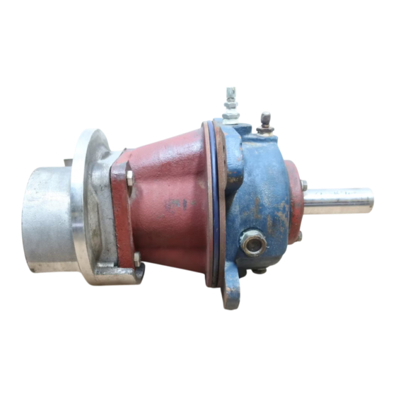
DIMENSIONS: INCHES [MILLIMETERS] NOTE: OPTIONAL ASA OR DIN STANDARD SUCTION & DISCHARGE SPOOL FLANGES AVAILABLE Figure 1. Pump Model T3A61-B PREINSTALLATION INSPECTION a. Inspect the pump for cracks, dents, damaged threads, and other obvious damage. The pump assembly was inspected and tested be- b. -
Page 8: Positioning Pump
OM−01932 T SERIES c. Carefully read all warnings and cautions con- tained in this manual or affixed to the pump, and perform all duties indicated. Note the di- rection of rotation indicated on the pump. The pump assembly can be seriously Check that the pump shaft rotates counter- damaged if the cables or chains used to lift clockwise when facing the impeller. -
Page 9: Connections To Pump
T SERIES OM−01932 tially increase friction loss. If elbows are necessary, Strainers use the long-radius type to minimize friction loss. If a strainer is furnished with the pump, be certain to use it; any spherical solids which pass through a Connections to Pump strainer furnished with the pump will also pass through the pump itself. -
Page 10: Suction Line Positioning
OM−01932 T SERIES tance equal to at least 3 times the diameter of the NOTE suction pipe. The pipe submergence required may be reduced by installing a standard pipe increaser fitting at the Suction Line Positioning end of the suction line. The larger opening size will reduce the inlet velocity. -
Page 11: Automatic Air Release Valve
T SERIES OM−01932 the discharge line is open, this air will be vented Rupp distributor, or contact the Gorman-Rupp through the discharge. However, if a check valve Company for selection of an Automatic Air Release has been installed in the discharge line, the dis- Valve to fit your application. -
Page 12: Theory Of Operation
OM−01932 T SERIES pass line, and then close automatically when the pump is fully primed and pumping at full capacity. Theory of Operation Some leakage (1 to 5 gallons [3.8 to 19 liters] per minute) will occur when the Figures 3 and 4 show a cross-sectional view of the valve is fully closed. -
Page 13: Alignment
T SERIES OM−01932 DISCHARGE PIPE CLEAN-OUT COVER INSTALL AIR RELEASE VALVE IN HORIZONTAL POSITION DISCHARGE CHECK VALVE 90_ LONG RADIUS ELBOW SUPPORT PUMP DISCHARGE BRACKET SELF-PRIMING CENTRIFUGAL PUMP BLEED LINE 1" (25,4 MM) DIA. MIN. (CUSTOMER FUR- NISHED) EXTEND 6" SUCTION (152 MM) BELOW LINE... -
Page 14: Coupled Drives
OM−01932 T SERIES When checking alignment, disconnect the power source to ensure that the pump will remain inoperative. Adjusting the alignment in one direction Figure 6B. Aligning Non-Spider may alter the alignment in another direc- Type Couplings tion. check each procedure after altering Check parallel adjustment by laying a straightedge alignment. - Page 15 T SERIES OM−01932 they will slip; if the belts are too tight, there will be DRIVE BELT TENSIONING excessive power loss and possible bearing failure. Select pulleys that will match the proper speed ra- General Rules of Tensioning tio; overspeeding the pump may damage both For new drive belts, check the tension after 5, 20 pump and power source.
-
Page 16: Operation − Section C
OM−01932 T-SERIES OPERATION − SECTION C Review all SAFETY information in Section A. Add liquid to the pump casing when: 1. The pump is being put into service for the Follow the instructions on all tags, labels and de- first time. cals attached to the pump. -
Page 17: Operation
OM−01932 T-SERIES If rotation is incorrect on a three-phase motor, have pressure, and cause the pump casing to a qualified electrician interchange any two of the rupture or explode. three phase wires to change direction. If rotation is Leakage incorrect on a single-phase motor, consult the liter- ature supplied with the motor for specific instruc- No leakage should be visible at pump mating sur- tions. -
Page 18: Strainer Check
OM−01932 T-SERIES Strainer Check head, gradually close the discharge throttling valve before stopping the pump. If a suction strainer has been shipped with the After stopping the pump, lock out or disconnect pump or installed by the user, check the strainer the power source to ensure that the pump will re- regularly, and clean it as necessary. - Page 19 T SERIES OM−01932 TROUBLESHOOTING − SECTION D Review all SAFETY information in Section A. Before attempting to open or service the pump: 1. Familiarize yourself with this manual. 2. Lock out or disconnect the power source to ensure that the pump will remain inoperative.
- Page 20 OM−01932 T SERIES TROUBLE POSSIBLE CAUSE PROBABLE REMEDY Air leak in suction line. Correct leak. PUMP STOPS OR FAILS TO DELIVER Lining of suction hose collapsed. Replace suction hose. RATED FLOW OR PRESSURE Leaking or worn seal or pump gasket. Check pump vacuum.
- Page 21 T SERIES OM−01932 TROUBLE POSSIBLE CAUSE PROBABLE REMEDY EXCESSIVE NOISE Cavitation in pump. Reduce suction lift and/or friction losses in suction line. Record vac- uum and pressure gauge readings and consult local representative or factory. Pumping entrained air. Locate and eliminate source of air bubble.
- Page 22 OM−01932 T SERIES Preventive Maintenance Schedule Service Interval* Item Daily Weekly Monthly Semi- Annually Annually General Condition (Temperature, Unusual Noises or Vibrations, Cracks, Leaks, Loose Hardware, Etc.) Pump Performance (Gauges, Speed, Flow) Bearing Lubrication Seal Lubrication (And Packing Adjustment, If So Equipped) V-Belts (If So Equipped) Air Release Valve Plunger Rod (If So Equipped) Front Impeller Clearance (Wear Plate)
- Page 23 PUMP MAINTENANCE AND REPAIR − SECTION E MAINTENANCE AND REPAIR OF THE WEARING PARTS OF THE PUMP WILL MAINTAIN PEAK OPERATING PERFORMANCE. STANDARD PERFORMANCE FOR PUMP MODEL T3A61-B Based on 70_ F (21_ C) clear water at sea level Contact the Gorman-Rupp Company to verify per- formance or part numbers.
- Page 24 OM−01932 T SERIES SECTION DRAWING TOP VIEW Figure 1. Pump Model T3A61−B, /F, /FM, /WW PAGE E − 2 MAINTENANCE & REPAIR...
- Page 25 OM−01932 T SERIES PARTS LIST Pump Model T3A61−B, /F, /FM, /WW (From S/N 1109105 up) If your pump serial number is followed by an N", your pump is NOT a standard production model. Contact the Gorman-Rupp Company to verify part numbers. ITEM PART NAME PART...
- Page 26 OM−01932 T SERIES SECTION DRAWING Figure 2. 44163−213 Repair Rotating Assembly PAGE E − 4 MAINTENANCE & REPAIR...
- Page 27 OM−01932 T SERIES PARTS LIST 44163−213 Repair Rotating Assembly Note: Order complete Repair Rotating Assembly for /WW model from the Pump Model Assembly Parts List on page E−3. Repair Rotating Assembly for /WW models include all of the standard parts listed below. ITEM PART NAME PART...
- Page 28 OM−01932 T SERIES PUMP AND SEAL DISASSEMBLY AND REASSEMBLY Before attempting to open or service the Review all SAFETY information in Section A. pump: 1. Familiarize yourself with this man- ual. Follow the instructions on all tags, label and decals attached to the pump.
- Page 29 T SERIES OM−01932 Suction Check Valve Removal Turn Counterclockwise (Figure 1) If the check valve assembly (30) is to be serviced, remove the check valve pin (31), reach through the back cover opening and pull the complete assem- Lathe Dog Arm bly from the suction flange (26).
- Page 30 OM−01932 T SERIES Use caution when lifting the rotating assembly to avoid injury to personnel or damage to the assem- bly. Shaft and bearing disassembly in the field Remove the bearing housing O-ring (8). is not recommended. These operations should be performed only in a properly- equipped shop by qualified personnel.
- Page 31 T SERIES OM−01932 Position the inboard oil seal (4) in the bearing hous- ing bore with the lip positioned as shown in Figure 2. Press the oil seal into the housing until the face is just flush with the machined surface on the hous- Bearings must be kept free of all dirt and ing.
- Page 32 OM−01932 T SERIES seat bore in the seal plate for dirt, nicks and burrs, and remove any that exist. The stationary seat bore must be completely clean before installing the seal. When installing the bearings onto the shaft, never press or hit against the outer The seal is not normally reused because wear pat- race, balls, or ball cage.
- Page 33 T SERIES OM−01932 RETAINER SEAL PLATE SPRING O-RINGS IMPELLER IMPELLER SHIMS IMPELLER SHAFT STATIONARY ROTATING ELEMENT ELEMENT BELLOWS SEAL WASHER SPRING CENTERING STATIONARY WASHER DRIVE BAND SEAT Figure 5. 46512−047 Seal Assembly Install the seal spring, seal washer (22), and spring centering washer.
- Page 34 OM−01932 T SERIES Install the same thickness of impeller adjusting the pump casing using the installation tool. Be shims (23) as previously removed. Apply ‘Never- careful not to damage the O-ring. Seez’ or equivalent to the shaft threads and screw Install the four sets of rotating assembly adjusting the impeller onto the shaft until tight.
- Page 35 T SERIES OM−01932 Back Cover Installation threads. Position the valve as shown in Figure 1 with the discharge port pointing down. (Figure 1) Final Pump Assembly If the wear plate (12) was removed for replace- ment, carefully center it on the back cover and se- (Figure 1) cure it with the hardware (13 and 14).
- Page 36 OM−01932 T SERIES quired, add SAE No. 30 non-detergent oil through the hole for the air vent (8). Do not over-lubricate. Over-lubrication can cause the bearings to over- heat, resulting in premature bearing failure. Monitor the condition of the bearing lubri- cant regularly for evidence of rust or mois- ture condensation.
- Page 37 For U.S. and International Warranty Information, Please Visit www.grpumps.com/warranty or call: U.S.: 419−755−1280 International: +1−419−755−1352 For Canadian Warranty Information, Please Visit www.grcanada.com/warranty or call: 519−631−2870 THE GORMAN-RUPP COMPANY D MANSFIELD, OHIO GORMAN-RUPP OF CANADA LIMITED ST. THOMAS, ONTARIO, CANADA...
Need help?
Do you have a question about the T3A61-B and is the answer not in the manual?
Questions and answers