Table of Contents
Advertisement
Quick Links
CDSW
OM-03199-OB01
May 27, 1988
Rev. F 11/25/02
INSTALLATION, OPERATION,
AND MAINTENANCE MANUAL
WITH PARTS LIST
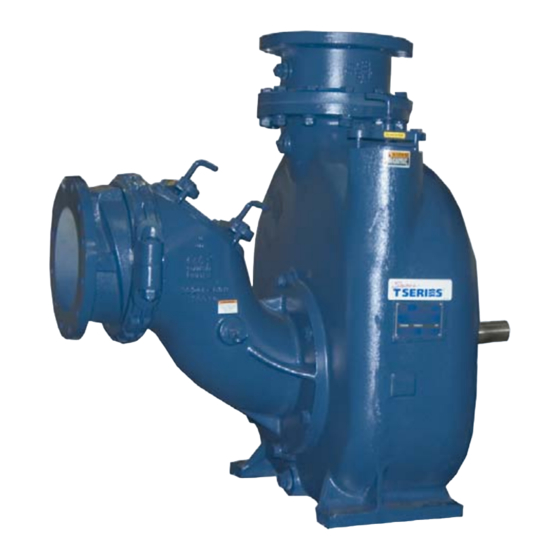
T-SERIES PUMP
MODEL
T10A65-B
THE GORMAN-RUPP COMPANY D MANSFIELD, OHIO
GORMAN-RUPP OF CANADA LIMITED
ST. THOMAS, ONTARIO, CANADA
D
Printed in U.S.A.
www.gormanrupp.com
Copyright by the Gorman-Rupp Company
E
Advertisement
Table of Contents

Related Manuals for GORMAN-RUPP PUMPS T10A65-B


Summary of Contents for GORMAN-RUPP PUMPS T10A65-B
- Page 1 May 27, 1988 Rev. F 11/25/02 INSTALLATION, OPERATION, AND MAINTENANCE MANUAL WITH PARTS LIST T-SERIES PUMP MODEL T10A65-B THE GORMAN-RUPP COMPANY D MANSFIELD, OHIO GORMAN-RUPP OF CANADA LIMITED ST. THOMAS, ONTARIO, CANADA Printed in U.S.A. www.gormanrupp.com Copyright by the Gorman-Rupp Company...
- Page 2 TABLE OF CONTENTS INTRODUCTION ..........PAGE I --- 1 SAFETY --- SECTION A .
-
Page 3: Table Of Contents
TABLE OF CONTENTS (continued) PUMP MAINTENANCE AND REPAIR --- SECTION E ....PAGE E --- 1 PERFORMANCE CURVE ........... PAGE E --- 1 PARTS LISTS: Pump Model... - Page 4 T SERIES OM -- 03199 INTRODUCTION Thank You for purchasing a Gorman-Rupp pump. Rupp pump. Read this manual carefully to learn how to safely This pump is a T Series, semi-open impeller, self- install and operate your pump. Failure to do so priming centrifugal model with a suction check could result in personal injury or damage to the valve.
- Page 5 T SERIES OM -- 03199 SAFETY --- SECTION A This information applies to T Series ba- 5. Close the suction and discharge sic pumps. Gorman-Rupp has no con- valves. trol over or particular knowledge of the 6. Vent the pump slowly and cau- power source which will be used.
- Page 6 T SERIES OM -- 03199 Do not operate the pump against a Use lifting and moving equipment in closed discharge valve for long periods good repair and with adequate capacity of time. If operated against a closed dis- to prevent injuries to personnel or dam- charge valve, pump components will age to equipment.
- Page 7 OUTLINE DRAWING NOTE: OPTIONAL ASA OR DIN STANDARD SPOOL FLANGES AVAILABLE Figure 1. Pump Model T10A65-B PREINSTALLATION INSPECTION a. Inspect the pump for cracks, dents, damaged threads, and other obvious damage.
- Page 8 OM -- 03199 T SERIES Mounting c. Carefully read all warnings and cautions con- tained in this manual or affixed to the pump, Locate the pump in an accessible place as close as and perform all duties indicated. Note the di- practical to the liquid being pumped.
- Page 9 T SERIES OM -- 03199 Gauges Sealing Since even a slight leak will affect priming, head, Most pumps are drilled and tapped for installing and capacity, especially when operating with a discharge pressure and vacuum suction gauges. high suction lift, all connections in the suction line If these gauges are desired for pumps that are not should be sealed with pipe dope to ensure an air- tapped, drill and tap the suction and discharge...
- Page 10 OM -- 03199 T SERIES Figure 2. Recommended Minimum Suction Line Submergence vs. Velocity DISCHARGE LINES If the application involves a high discharge Siphoning head, gradually close the discharge throttling valve before stopping the pump. Do not terminate the discharge line at a level lower than that of the liquid being pumped unless a si- Bypass Lines phon breaker is used in the line.
- Page 11 T SERIES OM -- 03199 minimize the chance of plugging. In low discharge head applications (less than 30 If a manual shut-off valve is installed in feet), it is recommended that the bypass line be run a bypass line, it must not be left closed back to the wet well, and located 6 inches below during operation.
- Page 12 OM -- 03199 T SERIES During the priming cycle, air from the pump casing When the pump shuts down, the spring returns the flows through the bypass line, and passes through diaphragm to its original position. Any solids that the Air Release Valve to the wet well (Figure 3). may have accumulated in the diaphragm chamber settle to the bottom and are flushed out during the next priming cycle.
- Page 13 T SERIES OM -- 03199 DISCHARGE PIPE CLEAN-OUT COVER INSTALL AIR RELEASE VALVE IN HORIZONTAL POSITION DISCHARGE CHECK VALVE 90_ LONG RADIUS ELBOW SUPPORT PUMP DISCHARGE BRACKET SELF-PRIMING CENTRIFUGAL PUMP BLEED LINE 1” (25,4 MM) DIA. MIN. (CUSTOMER FUR- NISHED) EXTEND 6” SUCTION (152 MM) BELOW LINE...
- Page 14 OM -- 03199 T SERIES When checking alignment, disconnect the power source to ensure that the pump will remain inoperative. Figure 6B. Aligning Non-Spider Type Cou- Adjusting the alignment in one direction plings may alter the alignment in another direc- tion.
- Page 15 T SERIES OM -- 03199 they will slip; if the belts are too tight, there will be excessive power loss and possible bearing failure. Select pulleys that will match the proper speed ra- tio; overspeeding the pump may damage both Do not operate the pump without the pump and power source.
- Page 16 OM -- 03199 T SERIES OPERATION --- SECTION C Review all SAFETY information in Section A. 1. The pump is being put into service for the first time. Follow the instructions on all tags, labels and de- 2. The pump has not been used for a consider- cals attached to the pump.
- Page 17 OM -- 03199 T SERIES pressure, and cause the pump casing to three phase wires to change direction. If rotation is incorrect on a single-phase motor, consult the liter- rupture or explode. ature supplied with the motor for specific instruc- tions.
- Page 18 OM -- 03199 T SERIES Strainer Check head, gradually close the discharge throttling valve before stopping the pump. If a suction strainer has been shipped with the After stopping the pump, disconnect the power pump or installed by the user, check the strainer regularly, and clean it as necessary.
- Page 19 T SERIES OM -- 03199 TROUBLESHOOTING --- SECTION D Review all SAFETY information in Section A. Before attempting to open or service the pump: 1. Familiarize yourself with this man- ual. 2. Lock out or disconnect the power source to ensure that the pump will remain inoperative.
- Page 20 OM -- 03199 T SERIES TROUBLE POSSIBLE CAUSE PROBABLE REMEDY PUMP STOPS OR Impeller or other wearing parts worn Replace worn or damaged parts. FAILS TO DELIVER or damaged. Check that impeller is properly RATED FLOW OR centered and rotates freely. PRESSURE (cont.) Impeller clogged.
- Page 21 T SERIES OM -- 03199 PREVENTIVE MAINTENANCE equipped) between regularly scheduled inspec- tions can indicate problems that can be corrected Since pump applications are seldom identical, and before system damage or catastrophic failure oc- pump wear is directly affected by such things as curs.
-
Page 22: Pump Maintenance And Repair
PUMP MAINTENANCE AND REPAIR --- SECTION E MAINTENANCE AND REPAIR OF THE WEARING PARTS OF THE PUMP WILL MAINTAIN PEAK OPERATING PERFORMANCE. STANDARD PERFORMANCE FOR PUMP MODEL T10A65-B Based on 70_ F (21_ C) clear water at sea level Contact the Gorman-Rupp Company to verify per- formance or part numbers. - Page 23 OM -- 03199 T SERIES SECTION DRAWING Figure 1. Pump Model T10A65---B PAGE E -- 2 MAINTENANCE & REPAIR...
-
Page 24: Parts Lists
OM -- 03199 T SERIES PARTS LIST Pump Model T10A65---B (S/N 928563 Up) If your pump serial number is followed by an “N”, your pump is NOT a standard production model. Contact the Gorman-Rupp Company to verify part numbers. ITEM PART NAME PART MAT’L... - Page 25 OM -- 03199 T SERIES SECTION DRAWING DRIVE END VIEW Figure 2. 44163---137 Repair Rotating Assembly PAGE E -- 4 MAINTENANCE & REPAIR...
- Page 26 OM -- 03199 T SERIES PARTS LIST 44163---137 Repair Rotating Assembly ITEM PART NAME PART MAT’L ITEM PART NAME PART MAT’L NUMBER CODE NUMBER CODE BRG HSG DRAIN PLUG 17090 IMPELLER 38615--- 014 1718H IMPELLER SHIM SET 5091 17090 SEAL ASSEMBLY 46512--- 192 --- --- --- SEAL CVTY DRAIN PLUG...
-
Page 27: Pump And Seal Disassembly And Reassembly
OM -- 03199 T SERIES PUMP AND SEAL DISASSEMBLY 7. Drain the pump. AND REASSEMBLY Review all SAFETY information in Section A. Use lifting and moving equipment in Follow the instructions on all tags, label and decals good repair and with adequate capacity attached to the pump. - Page 28 T SERIES OM -- 03199 ommended that it be removed through the suction dog sharply in a counterclockwise direction (when head opening. facing the drive end of the shaft). When the impeller breaks loose, remove the wood block and lathe (Figure 2) dog.
-
Page 29: Impeller Removal
OM -- 03199 T SERIES Impeller Removal should be performed only in a properly equipped shop by qualified personnel. (Figure 2) Remove the bearing housing drain plug (22) and Unscrew the impeller (1) in a counterclockwise di- drain the lubricant. Clean and reinstall the drain rection (when facing the impeller). -
Page 30: Shaft And Bearing Reassembly And Installation
T SERIES OM -- 03199 Inspect the shaft for distortion, nicks or scratches, or for thread damage on the impeller end. Dress small nicks and burrs with a fine file or emery cloth. Replace the shaft if defective. Bearings must be kept free of all dirt and Position the inboard oil seal (6) in the bearing hous- foreign material. -
Page 31: Seal Reassembly And Installation
OM -- 03199 T SERIES BALL LOADING BALL LOADING GROOVE POSITIONED GROOVE POSITIONED TOWARD IMPELLER AWAY FROM IMPELLER LOADING LOADING GROOVE GROOVE DIRECTION OF DIRECTION OF THRUST THRUST INSTALLATION OF NEW DEPARTURE OR INSTALLATION OF MRC/SKF 5300M OR BCA/FEDERAL MOGAL 5300W SERIES BEARINGS FAFNIR 5300W SERIES BEARINGS (OPEN OR ENCLOSED IMPELLERS) (OPEN OR ENCLOSED IMPELLERS) - Page 32 T SERIES OM -- 03199 Inspect the seal components for wear, scoring, faces to ensure that they are free of any foreign grooves, and other damage that might cause leak- matter. age. Clean and polish the seal area on the impeller shaft.
-
Page 33: Impeller Installation
OM -- 03199 T SERIES Install the seal spring. Lubricate the seal as indi- and install the impeller washer (27) and capscrew; cated in LUBRICATION after the impeller is in- torque the capscrew to 90 ft. lbs. (1080 in. lbs. or stalled. -
Page 34: Suction Head And Wear Plate Installation
T SERIES OM -- 03199 Suction Head And Wear Plate Installation valve, apply ‘Loctite Pipe Sealant With Teflon No. 592’, or equivalent compound, on the relief valve (Figure 1) threads. Position the valve as shown in Figure 1 with the discharge port pointing down. Clean any debris from the contacting surfaces in the pump casing that might prevent a good seal with the suction head or interfere with the wear... -
Page 35: Power Source
OM -- 03199 T SERIES tioned horizontally to provide proper drainage. cant regularly for evidence of rust or mois- ture condensation. This is especially im- portant in areas where variable hot and Under normal conditions, drain the bearing hous- cold temperatures are common. ing once each year and refill with approximately 32 ounces (0,95 liter) of clean oil. - Page 36 For U.S. and International Warranty Information, Please Visit www.grpumps.com/warranty or call: U.S.: 419−755−1280 International: +1−419−755−1352 For Canadian Warranty Information, Please Visit www.grcanada.com/warranty or call: 519−631−2870 THE GORMAN-RUPP COMPANY D MANSFIELD, OHIO GORMAN-RUPP OF CANADA LIMITED ST. THOMAS, ONTARIO, CANADA...
Need help?
Do you have a question about the T10A65-B and is the answer not in the manual?
Questions and answers