Moxa Technologies AirWorks AWK-5232 Quick Installation Manual
Hide thumbs
Also See for AirWorks AWK-5232:
- User manual (81 pages) ,
- Quick installation manual (16 pages)
Table of Contents
Advertisement
Quick Links
Quick Installation Guide
Moxa Americas:
Toll-free: 1-888-669-2872
Tel:
1-714-528-6777
Fax:
1-714-528-6778
Moxa Europe:
Tel:
+49-89-3 70 03 99-0
Fax:
+49-89-3 70 03 99-99
Moxa India:
Tel:
+91-80-4172-9088
Fax:
+91-80-4132-1045
AWK-5232
Moxa AirWorks
Edition 3.0, February 2017
Technical Support Contact Information
www.moxa.com/support
2017 Moxa Inc. All rights reserved.
Moxa China (Shanghai office):
Toll-free: 800-820-5036
Tel:
+86-21-5258-9955
Fax:
+86-21-5258-5505
Moxa Asia-Pacific:
Tel:
+886-2-8919-1230
Fax:
+886-2-8919-1231
P/N: 1802052320012
*1802052320012*
Advertisement
Table of Contents

Related Manuals for Moxa Technologies AirWorks AWK-5232


Summary of Contents for Moxa Technologies AirWorks AWK-5232
- Page 1 AWK-5232 Quick Installation Guide Moxa AirWorks Edition 3.0, February 2017 Technical Support Contact Information www.moxa.com/support Moxa Americas: Moxa China (Shanghai office): Toll-free: 1-888-669-2872 Toll-free: 800-820-5036 Tel: 1-714-528-6777 Tel: +86-21-5258-9955 Fax: 1-714-528-6778 Fax: +86-21-5258-5505 Moxa Europe: Moxa Asia-Pacific: Tel: +49-89-3 70 03 99-0 Tel: +886-2-8919-1230 Fax:...
-
Page 2: Package Checklist
Overview The AWK-5232 802.11 a/b/g/n dual-RF wireless AP/Bridge/Client provides a flexible and highly reliable solution for your industrial wireless networks. The AWK-5232 is rated to operate at temperatures ranging from 0 to 60°C for standard models and -40 to 75°C for extended temperature models, and it is rugged enough for industrial applications. - Page 3 Step 3: Set up the computer’s IP address Set an IP address on the same subnet as the AWK-5232. Since the AWK-5232’s default IP address is 192.168.127.253, and the subnet mask is 255.255.255.0, you should set the IP address of the computer to 192.168.127.xxx and subnet mask to 255.255.255.0.
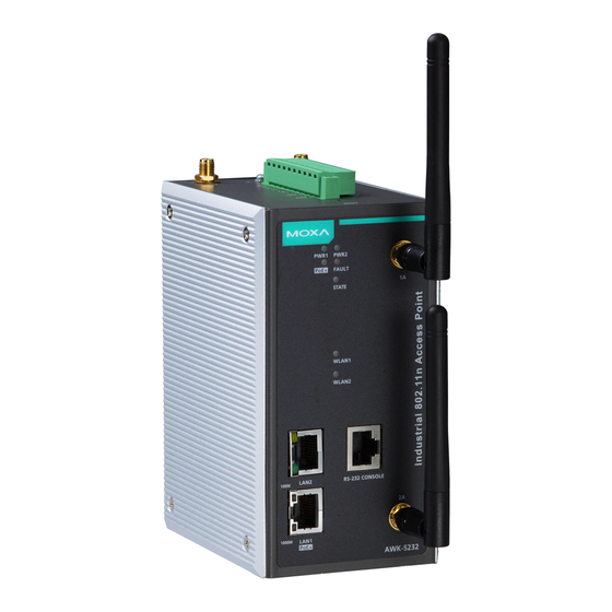
- Page 4 Panel Layout of the AWK-5232 1. Grounding screw 2. Terminal block for PWR1, PWR2, relay, DI1, and DI2 3. Reset button 4. 1B antenna port (1A and 1B are shared same RF module) 2B antenna port (2A and 2B are shared same RF module) 6.
-
Page 5: Mounting Dimensions
Mounting Dimensions DIN-Rail Mounting The aluminum DIN-rail attachment plate should be fixed to the back panel of the AWK-5232 when you take it out of the box. If you need to reattach the DIN-rail attachment plate to the AWK-5232, make sure the stiff metal spring is situated towards the top, as shown in the figures below: STEP 1: STEP 2:... -
Page 6: Wall Mounting (Optional)
Wall Mounting (optional) For transportation applications that require an EN50155 certification report, you should purchase the optional wall mount for the AWK-5232, since the wall mount has passed EN50155 testing. The wall mount is also convenient for other applications that require mounting the AWK-5232 to a wall. -
Page 7: Wiring Requirements
Wiring Requirements WARNING Safety First! Be sure to disconnect the power cord before installing and/or wiring your Moxa AWK-5232. WARNING Safety First! Calculate the maximum possible current in each power wire and common wire. Observe all electrical codes dictating the maximum current allowed for each wire size. - Page 8 Grounding the Moxa AWK-5232 Grounding and wire routing help limit the effects of noise due to electromagnetic interference (EMI). Run the ground connection from the ground screw to the grounding surface prior to connecting devices. ATTENTION This product is intended to be mounted to a well-grounded mounting surface, such as a metal panel.
-
Page 9: Wiring The Redundant Power Inputs
Arrester Accessories SA-NMNF-01: Surge arrester, N-type (male) to N-type (female) • • SA-NFNF-01: Surge arrester, N-type (female) to N-type (female) Wiring the Redundant Power Inputs The top two pairs of contacts of the 10-contact terminal block connector on the AWK-5232’s top panel are used for the AWK-5232’s two DC inputs. Top and front views of the terminal block connector is shown here. -
Page 10: Wiring The Relay Contact
Wiring the Relay Contact The AWK-5232 has one relay output, which consists of the two contacts of the terminal block on the AWK-5232’s top panel. Refer to the previous section for detailed instructions on how to connect the wires to the terminal block connector, and how to attach the terminal block connector to the terminal block receptor. -
Page 11: Communication Connections
Communication Connections 10/100BaseT(X) Ethernet Port Connection The 10/100BaseT(X) ports located on the AWK-5232’s front panel are used to connect to Ethernet-enabled devices. The pinouts for both MDI (NIC-type) ports and MDI-X (HUB/Switch-type) ports are shown below: MDI Port Pinouts MDI-X Port Pinouts 8-pin RJ45 Signal Signal... -
Page 12: Led Indicators
NOTE The pin numbers for DB9 and DB25 male connectors, and hole numbers for DB9 and DB25 female connectors are labeled on the connector strip. However, the numbers are typically quite small, so you may need to use a magnifying glass to see the numbers clearly. -
Page 13: Specifications
Color State Description TP Port (LAN1, LAN2) LED Indicators (Port Interface) TP port’s 100 Mbps link is active. 100M Yellow Blinking Data is being transmitted at 100 Mbps TP port’s 100 Mbps link is inactive. TP port’s 1000 Mbps link is active. 1000M Green Blinking... - Page 14 Transmitter Power 802.11b: Typ. 18±1.5 dBm @ 1 to 11 Mbps 802.11g: Typ. 18±1.5 dBm @ 6 to 24 Mbps, Typ. 17±1.5 dBm @ 36 to 48 Mbps, Typ. 15±1.5 dBm @ 54 Mbps 802.11n (2.4 GHz): Typ. 14±1.5 dBm @ MCS15 20 MHz 802.11a: Typ.
- Page 15 LAN Ports 2, RJ45, 10/100/1000BaseT(X), auto negotiation speed F/H duplex mode, and auto MDI/MDI-X connection. Console Port 1, RS-232 (RJ45-type) Reset Present LED Indicators PWR1, PWR2, PoE+, FAULT, STATE, WLAN1, WLAN2, 100M, 1000M Alarm Contact 1 relay output with current carrying capacity of 1 A @ (Digital Output) 24 VDC Digital Inputs...
- Page 16 ATTENTION The AWK-5232 is NOT a portable mobile device and should be located at least 20 cm away from the human body. The AWK-5232 is NOT designed for the general public. A well-trained technician is required to deploy the AWK-3191 units and safely establish a wireless network.
Need help?
Do you have a question about the AirWorks AWK-5232 and is the answer not in the manual?
Questions and answers