Table of Contents
Advertisement
Quick Links
B B
D D
2 2
0 0
0 0
S S
B B
D D
2 2
0 0
0 0
S S
G
G
BEFORE RETURNING THIS PRODUCT FOR ANY
BEFORE YOU CALL, HAVE THE FOLLOWING INFORMATION AVAILABLE, CATALOG NO., TYPE NO., AND DATE CODE . IN MOST
CASES, A BLACK & DECKER REPRESENTATIVE CAN RESOLVE THE PROBLEM OVER THE PHONE. IF YOU HAVE A
SUGGESTION OR COMMENT, GIVE US A CALL. YOUR FEEDBACK IS VITAL TO BLACK & DECKER.
SAVE THIS MANUAL FOR FUTURE REFERENCE.
VEA EL ESPAÑOL EN LA CONTRAPORTADA.
POUR LE FRANÇAIS, VOIR LA COUVERTURE ARRIÈRE.
INSTRUCTIVO DE OPERACIÓN, CENTROS DE SERVICIO Y
PÓLIZA DE GARANTÍA. ADVERTENCIA: LÉASE ESTE
INSTRUCTIVO ANTES DE USAR EL PRODUCTO.
D D
1 1
0 0
D D
1 1
0 0
i i
n n
i i
n n
INSTRUCTION MANUAL
T
T
HANK
YOU
FOR
CHOOSING
HANK
YOU
FOR
CHOOSING
.B
.B
O
T
O
WWW
LACKAND
O
T
O
WWW
LACKAND
T
O
REGISTER
T
O
REGISTER
REASON PLEASE CALL 1-800-544-6986
T T
( (
2 2
5 5
4 4
M M
M M
) )
( (
2 2
5 5
4 4
M M
M M
) )
B
& D
B
& D
LACK
LACK
D
.
D
.
ECKER
COM
ECKER
COM
YOUR
NEW
PRODUCT
YOUR
NEW
PRODUCT
A A
B B
L L
E E
S S
T T
A A
B B
L L
E E
S S
!
!
ECKER
ECKER
/N
O
/N
O
EW
WNER
EW
WNER
.
.
A A
W W
A A
W W
Advertisement
Table of Contents

Related Manuals for Black & Decker BD200SD


Summary of Contents for Black & Decker BD200SD
- Page 1 INSTRUCTION MANUAL & D & D HANK CHOOSING LACK ECKER HANK CHOOSING LACK ECKER LACKAND ECKER WNER LACKAND ECKER WNER REGISTER YOUR PRODUCT REGISTER YOUR PRODUCT BEFORE RETURNING THIS PRODUCT FOR ANY REASON PLEASE CALL 1-800-544-6986 BEFORE YOU CALL, HAVE THE FOLLOWING INFORMATION AVAILABLE, CATALOG NO., TYPE NO., AND DATE CODE . IN MOST CASES, A BLACK &...
-
Page 2: Table Of Contents
TABLE OF CONTENTS IMPORTANT SAFETY INSTRUCTIONS ............2 SAFETY GUIDELINES . -
Page 3: Safety Guidelines
SAFETY GUIDELINES - DEFINITIONS It is important for you to read and understand this manual. The information it contains relates to protecting YOUR SAFETY and PREVENTING PROBLEMS. The symbols below are used to help you recognize this information. Indicates an imminently hazardous situation which, if not avoided, will result in death or serious injury. Indicates a potentially hazardous situation which, if not avoided, could result in death or serious injury. -
Page 4: Important Safety Instructions
GENERAL SAFETY RULES READ AND UNDERSTAND ALL WARNINGS AND OPERATING INSTRUCTIONS BEFORE USING THIS EQUIPMENT. Failure to follow all instructions listed below, may result in electric shock, fire, and/or serious personal injury or property damage. IMPORTANT SAFETY INSTRUCTIONS 1. FOR YOUR OWN SAFETY, READ THE INSTRUCTION 14. -
Page 5: Additional Specific Safety Rules
ADDITIONAL SPECIFIC SAFETY RULES READ AND UNDERSTAND ALL INSTRUCTIONS. FAILURE TO FOLLOW THESE INSTRUCTIONS MAY RESULT IN ELECTRICAL SHOCK, FIRE AND / OR SERIOUS INJURY. DO NOT OPERATE THIS MACHINE until it is 10. CUTTING THE WORKPIECE WITHOUT THE USE OF assembled and installed according to the instructions. - Page 6 POWER CONNECTIONS A separate electrical circuit should be used for your machines. This circuit should not be less than #12 wire and should be protected with a 20 Amp time lag fuse. If an extension cord is used, use only 3-wire extension cords which have 3- prong grounding type plugs and matching receptacle which will accept the machine’s plug.
-
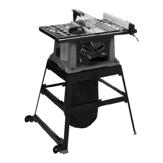
Page 7: Functional Description
FOREWORD Model BD200SD is a 10 inch Table Saw designed to give high quality performance with depth of cut capacity up to 3 inches (76mm) at 90° and 2 inches (51mm) at 45° for clean cutting of standard stock sizes. - Page 8 Fig. 2 Fig. 2 Parts Fig. 3 1. Rip Fence Fig. 3 Hardware 2. Splitter and Guard Assembly 3. Lock Handle for Rip Fence 1. M6x1x55mm Pan Head Screw (1) 4. Blade Raising and Lowering Handwheel 2. 1/4-20x2 inch Hex Head Screw (1) 5.
-
Page 9: Assembly
UNPACKING AND CLEANING Carefully unpack the machine and all loose items from the shipping container(s). Remove the protective coating from all unpainted surfaces. This coating may be removed with a soft cloth moistened with kerosene (do not use acetone, gasoline or lacquer thinner for this purpose). - Page 10 ATTACHING MITER GAUGE HOLDER DISCONNECT MACHINE FROM POWER SOURCE. Fig. 5 Fig. 6 Attach the spring clip (E) Fig. 5 to the miter gauge holder (A) using an M4x.7x10mm pan head screw (F), 3/16 inch external tooth lockwasher, (B) and M4x.7 hex nut. NOTE: The hex nut (G) Fig.
- Page 11 ASSEMBLING STAND 1. Attach the rubber feet (H) Fig. 11 to the bottom of each leg (F). Locate the two legs (F) which have holes at the bottom for attaching the wheel brackets (G) and brace (E). (Make sure wheels and brackets are properly oriented.
- Page 12 ATTACHING BLADE HEIGHT ADJUSTING HANDWHEEL 1. Insert an M6x1x55mm pan head screw (D) Fig. 14 through the handle (E). Attach the handle (E) to the handwheel (A) by threading the screw (D) clockwise into the handwheel. 2. Attach the handwheel (A) Fig. 15 to the shaft (B). Align the flat on the inside of the handwheel to the flat on the shaft. Fig.
- Page 13 Locate the 1/4-20x2 inch hex head screw (G) Fig. 18. Place the 1/4 inch internal tooth lockwasher (O) M6.4 flat washer (P) and the 1/4 inch external tooth lockwasher (R) on the screw (G). Position the recessed end (E) Fig. 19 of the splitter bracket (B) against the end of the pivot rod (F), and fasten using the assembly in STEP 3.
- Page 14 NOTE: Before tightening the wing nut (M) Fig. 23, make certain a gap of at least 1/8 inch is between the bottom edge of the splitter (N) and the top surface of the table (P) and that the protrusions (K) are inside the slot of the splitter assembly (H).
-
Page 15: Operation
MOVING THE SAW To move the saw, grasp the side of the table opposite of the wheels. Lift the saw so that it is slightly off the floor and pull the table to the desired location as shown. Not all floors are perfectly smooth, check both wheels each time you move the saw to ensure that they are not engaging the floor when the saw is at rest. - Page 16 BLADE TILT ADJUSTMENT To tilt the saw blade, loosen the lock handle (A) Fig. 32 and move the handwheel (B) until the blade is at the desired angle. Tighten the lock handle (A). NOTE: The lock handle (A) is spring-loaded. Pull out on the handle (A) and reposition it on the serrated stud located underneath the handle.
- Page 17 RIP FENCE OPERATION AND ADJUSTMENTS 1. To move the rip fence (A) Fig. 35 along the table, lift up the fence locking lever (B), slide the fence to the desired location on the table, and push down the fence locking lever (B). 2.
- Page 18 MITER GAUGE OPERATION AND ADJUSTMENTS For cross-cutting (blade set 90 degrees to the table), the miter gauge can be used in either table slot. For bevel cross-cutting (with the blade tilted), use the miter gauge in the right table slot only so that the blade will be tilted away from the miter gauge and your hands.
- Page 19 CHANGING THE BLADE DISCONNECT THE MACHINE FROM THE POWER SOURCE. USE ONLY 10 INCH DIAMETER SAW BLADES RATED FOR 4700 RPM OR HIGHER. USE ONLY SAW BLADES WITH 5/8 INCH ARBOR HOLES. 1. NOTE: One 7/8 inch wrench is supplied with the saw for changing the saw blade.
- Page 20 (B) can be fastened to the front of the miter gage by using two wood screws (C) through the holes provided in the miter gage body and into the wood-facing. NEVER USE THE FENCE AS A CUT-OFF GAGE WHEN CROSS-CUTTING. When cross-cutting a number of pieces to the same length, a block of wood (B) Fig.
- Page 21 feet, use a work support at the rear of the saw to keep the workpiece from falling off the saw table. 3. If the ripped work is less than 6 inches wide, a push stick should always be used to complete the feed, as shown in Fig.
- Page 22 1. Dadoing is cutting a rabbet or wide groove into the work. Most dado head sets are made up of two outside saws and four or five inside cutters, (Fig. 48A). Various combinations of saws and cutters are used to cut grooves from 1/8 inch to 13/16 inch for use in shelving, making joints, tenoning, grooving, etc.
- Page 23 CONSTRUCTING A PUSH STICK When ripping work less than 4 inches wide, a push stick should be used to complete the feed and could be easily made from scrap material by following the pattern shown in Fig. 53.
- Page 24 CONSTRUCTING A FEATHERBOARD Fig. 54, illustrates dimensions for making a typical featherboard. The material which the featherboard is constructed of, should be a straight piece of wood that is free of knots and cracks. Featherboards are used to keep the work in contact with the fence and table, as shown in Fig.
-
Page 25: Troubleshooting
TROUBLESHOOTING BE SURE TO FOLLOW SAFETY RULES AND INSTRUCTIONS TROUBLE! SAW WILL NOT START WHAT’S WRONG? WHAT TO DO… 1.Saw not plugged in. 1.Plug in saw. 2.Fuse blown or circuit breaker tripped. 2.Replace fuse or reset circuit breaker. 3.Cord damaged. 3.Have cord replaced by authorized service center. -
Page 26: Maintenance
MAINTENANCE KEEP MACHINE CLEAN LUBRICATION Periodically blow out all air passages with dry compressed machine Apply household floor paste wax to the table and air. All plastic parts should be cleaned with a soft damp cloth. extension table or other work surface weekly. NEVER use solvents to clean plastic parts. -
Page 27: Spanish
À À À À MODE D'EMPLOI MERCI D’A VOIR CHOISI BLACK & DECKER ! MERCI D’A VOIR CHOISI BLACK & DECKER ! VISITEZ VISITEZ LACKAND ECKER WNER LACKAND ECKER WNER POUR ENREGISTRER VOTRE NOUVEAU PRODUIT POUR ENREGISTRER VOTRE NOUVEAU PRODUIT AVANT DE RETOURNER CE PRODUIT POUR QUELQUE RAISON QUE CE SOIT, COMPOSER LE NUMÉRO SUIVANT : 1 800 544-6986... - Page 28 LIGNES DIRECTRICES EN MATIÈRE DE SÉCURITÉ — DÉFINITIONS Il est important que vous lisiez et compreniez ce mode d’emploi. Les informations qu’il contient concernent VOTRE SÉCURITÉ et visent à ÉVITER TOUT PROBLÈME. Les symboles ci-dessous servent à vous aider à reconnaître cette information.
- Page 29 RÈGLES GÉNÉRALES DE SÉCURITÉ LIRE ATTENTIVEMENT TOUTES LES MISES EN GARDE ET DIRECTIVES AVERTISSEMENT D’UTILISATION AVANT D’UTILISER CET ÉQUIPEMENT. À défaut de suivre les directives sous mentionnées, un choc électrique, un incendie, des dommages ou une blessure corporelle grave pourraient survenir. DIRECTIVES DE SÉCURITÉ...
- Page 30 RÈGLES DE SÉCURITÉ SPÉCIFIQUES SUPPLÉMENTAIRES LIRE ATTENTIVEMENT TOUTES LES MISES EN GARDE ET DIRECTIVES D’UTILISATION AVERTISSEMENT AVANT D’UTILISER CET ÉQUIPEMENT. À défaut de suivre les directives sous mentionnées, un choc électrique, un incendie, des dommages ou une blessure corporelle grave pourraient survenir.
- Page 31 CONNEXIONS ÉLECTRIQUES Un circuit électrique séparé doit être utilisé pour vos machines. Ce circuit doit utiliser un câble de calibre 12 au minimum et doit être protégé par un fusible temporisé de 20 A. Si vous utilisez une rallonge électrique, n’utiliser que des rallonges à...
- Page 32 INTRODUCTION Modèle BD200SD est une scie de table de 254 mm (10 po) conçue pour vous offrir une performance de haute qualité avec une profondeur de coupe jusqu’à 76 mm (3 po) à 90°, et 51 mm (2 po) à 45°, pour une coupe nette des pièces de taille standard.
- Page 33 5. (4) Vis hexagonales de M8x1,25x45 mm pour fixer la scie Fig. 4 Quincaillerie pour le socle au socle 6. (16) Boulons de carrosserie de M8x1,25x20 mm pour 1. (4) pattes (dont 2 sont perforées à la base pour la fixation assembler le socle du support de roue et de la traverse) 7.
- Page 34 FIXATION DU PORTE-JAUGE À ONGLET AVERTISSEMENT DÉBRANCHER L'APPAREIL DE LA SOURCE D’ALIMENTATION. Fixer l'attache à ressort (E) fig. 5 du porte-jauge à onglet (A) en utilisant une vis à tête cylindrique de M4x de 0,7 x 10 mm (F), une rondelle à denture extérieure de 3/16 po (4,8 mm), (B) et un écrou hexagonal M4x de 0,7. REMARQUE : l'écrou hexagonal (G) fig.
- Page 35 1. Positionner la lame à angle droit (90°) par rapport à la table puis la verrouiller en place. 2. Fixer le support du couteau séparateur (A) fig. 17 au support du couteau séparateur (B) à l'aide de deux vis à tête hexagonale de1/4-20x1/2 po (C) et deux rondelles à...
- Page 36 RÉGLAGE DE LA HAUTEUR DE LA LAME Pour régler la hauteur de la lame de la scie, tourner le volant (A) fig. 31. Tourner le volant en sens horaire abaisse la lame et le tourner dans le sens antihoraire la relève. RÉGLAGE DE L’INCLINAISON DE LA LAME Pour incliner la lame de la scie, desserrer la poignée de verrouillage (A) fig.
- Page 37 UTILISATION ET RÉGLAGES DE LA JAUGE À ONGLET Pour le tronçonnage (lame à 90 degrés de la table la jauge à onglet peut être utilisée dans l'une ou l'autre fente sur la table. Pour un tronçonnage en biseau (avec la lame inclinée) utiliser la jauge à onglet dans la fente droite de la table uniquement pour que la lame soit inclinée en s'éloignant de la jauge et de vos mains.
- Page 38 UNE DES RÈGLES D'UTILISATION D'UNE SCIE : NE JAMAIS SE SUSPENDRE SUR, NI TOUCHER AVERTISSEMENT LA PARTIE DE LA PIÈCE À DÉCOUPER. Tenir la pièce supportée, et non la pièce coupée. Le tronçonnage se poursuit jusqu’à ce que la pièce soit coupée en deux, et que la jauge à...
- Page 39 UTILISATION DU PAREMENT EN BOIS AUXILIAIRE FACE AU GUIDE LONGITUDINAL En exécutant certaines coupes spéciales – et si cette opération peut mettre l'accessoire de coupe en contact avec le guide – il faut ajouter un parement en bois (A) fig. 47A, d'un côté du guide longitudinal tel qu'illustré. Le parement en bois se fixe au guide avec des vis en bois à...
- Page 40 FABRICATION D’UNE PLANCHE EN ÉVENTAIL La figure 54 illustre les dimensions utilisées pour la fabrication d’une planche en éventail typique. Utiliser une pièce de bois droite exempte de noeuds et de fissures pour la fabrication de la planche en éventail. Les planches en éventail sont utilisées pour maintenir la pièce en contact avec le guide et la table, comme indiqué...
- Page 41 ACCESSOIRES Les accessoires recommandés pouvant être utilisés avec l’outil sont disponibles auprès de votre distributeur local ou centre de réparation autorisé. Pour tout renseignement concernant les accessoires, composer le : 1-800-544-6986 l’utilisation de tout accessoire non recommandé avec l’outil pourrait s’avérer dangereuse. RÉPARATION Tous les centres de réparation Black &...
- Page 42 MANUAL DE INSTRUCCIONES ¡GRACIAS POR ELEGIR BLACK & DECKER! VAYA A WWW.BLACKANDDECKER.COM/NEWOWNER PARA REGISTRAR SU NUEVO PRODUCTO. ANTES DE DEVOL VER ESTE PRODUCTO POR CUALQUIER MOTIVO, LLAME AL ANTES DE DEVOL VER ESTE PRODUCTO POR CUALQUIER MOTIVO, LLAME AL (55) 5326-7100 (55) 5326-7100...
-
Page 43: French
PAUTAS DE SEGURIDAD/DEFINICIONES Es importante para usted leer y entender este manual. La información que lo contiene relaciona a proteger SU SEGURIDAD y PREVENIR los PROBLEMAS. Los símbolos debajo de son utilizados para ayudarlo a reconocer esta información. Indica una situación de inminente riesgo, la cual, si no es evitada, causará la muerte o lesiones serias. Indica una situación potencialmente riesgosa, que si no es evitada, podría resultar en la muerte o lesiones serias. - Page 44 NORMAS GENERALES DE SEGURIDAD LEA Y COMPRENDA TODAS LAS ADVERTENCIAS Y LAS INSTRUCCIONES DE OPERACIÓN ANTES DE UTILIZAR ESTE EQUIPO. El incumplimiento de cualquiera de las instrucciones enumeradas abajo puede provocar descarga eléctrica, incendio o lesiones personales graves o daños a la propiedad. INSTRUCCIONES IMPORTANTES SOBRE SEGURIDAD UTILICE EL CORDÓN DE EXTENSIÓN ADECUADO.
- Page 45 REGLAS DE SEGURIDAD ADICIONALES PARA SIERRA DE MESA ES IMPORTANTE PARA USTED LEER Y ENTENDER ESTE MANUAL. EL INCUMPLIMIENTO DE LAS INSTRUCCIONES ENUMERADAS DEBAJO PUEDE PROVOCAR DESCARGA ELÉCTRICA, INCENDIO O LESIONES GRAVES. 11. NUNCA realice operaciones "a pulso". Utilice el tope-guía UTILICE ESTA MÁQUINA...
- Page 46 CONEXIONES A LA FUENTE DE ALIMENTACIÓN Debe utilizarse un circuito eléctrico independiente para las máquinas. Este circuito debe tener alambre de no menos del No. 12 y debe estar protegido con un fusible de acción retardada de 20 A. Si se utiliza un cordón de extensión, utilice únicamente cordones de extensión de tres alambres que tengan enchufes de tipo de conexión a tierra con tres terminales y un receptáculo coincidente que acepte el enchufe de la máquina.
- Page 47 INTRODUCCIÓN Modelo BD200SD es una sierra de mesa de 10" diseñada para brindar un rendimiento de alta calidad, con una capacidad de profundidad de corte de hasta 3" (76 mm) a 90° y 2" (51 mm) a 45°, para cortar limpiamente tamaños de material estándar.
- Page 48 DESEMPAQUETADO Y LIMPIEZA Desempaque cuidadosamente la máquina y todas las piezas sueltas que están en el contenedor o contenedores de transporte. Quite el revestimiento protector de todas las superficies no pintadas. Este revestimiento puede quitarse con un paño suave humedecido con queroseno (no utilice acetona, gasolina ni diluyente de laca para este fin). Después de realizar la limpieza, cubra las superficies no pintadas con una cera en pasta doméstica de buena calidad para pisos.
- Page 49 ENSAMBLADO DEL PORTADOR DE LA ESCUADRA DE INGLETES DESCONCTE LA MAQUINA DE LA FUENTE DE ALIMENTACION. 1. Ensamble fig. 5 del (E) del clip de resorte, el (A) del sostenedor de la galga de los ingletes según lo mostrado usando un tornillo de la pista de la cacerola de M4x.7x10mm (F), el (B) de la arandela de cierre del diente del 3/16" y la tuerca de tuerca hexagonal externos M4x.7.
- Page 50 ENSAMBLADO DEL VOLANTE DE INCLINACION Y ELEVADO DE HOJA Inserte el tornillo de M6x1x55 screw (D) Fig. 14, a través de la agarradera (E) y ensamble la agarradera (E) al volante de mano (A) mediante el roscado del tornillo (D) en el sentido de las manecillas del reloj hacia dentro del volante de mano.
- Page 51 TRASLADO DE LA SIERRA Para trasladar la sierra, tome el lado de la mesa opuesto a las ruedas. Levante apenas la sierra del suelo y empuje la mesa hasta la posición deseada como se muestra. No todos los pisos son totalmente uniformes, revise ambas ruedas cada vez que traslade la sierra para asegurarse de que no se traben en el piso cuando la sierra esté...
- Page 52 Coloque una escuadra (A) Fig. 34 sobre la mesa y contra la hoja, tal como se ilustra, y revise si la hoja se encuentra a 45 grados a la mesa. Si la hoja no se encuentra a 45 grados a la mesa, afloje el tornillo (C) Fig. 34unas cuantas vueltas y mueva el mecanismo de inclinación de hoja hasta (B) Fig.
- Page 53 CAMBIO DE LA HOJA DESCONECTE LA MÁQUINA DE LA FUENTE DE ALIMENTACIÓN. UTILICE HOJAS DE SIERRA CON UN DIÁMETRO DE 254 MM (10”) CALIFICADAS PARA 4700 RPM O MAYOR. UTILICE ÚNICAMENTE HOJAS DE SIERRA CON ORIFICIOS PARA MANDRIL DE 16 MM (5/8”). NOTA: Junto con la sierra se suministra una llave de 22,2 mm (7/8") para cambiar la hoja de la sierra.
- Page 54 UNA TOPE-GUIA SIEMPRE SE DEBE UTILIZAR PARA LAS OPERACIONES LA REALIZACIÓN DE CORTES AL HILO. NUNCA REALICE UNA OPERACIÓN QUE LA REALIZACIÓN DE CORTES AL HILO HECHO A PULSO. 1. Arranque el motor y haga avanzar la pieza de trabajo sujetándola hacia abajo y contra el tope-guía. No se sitúe nunca en la línea del corte de la sierra cuando realice cortes al hilo.
- Page 55 EL CONJUNTO DE PROTECTOR DE LA HOJA Y SEPARADOR NO SE PUEDE UTILIZAR CUANDO SE REALICEN OPERACIONES DE RANURADO Y SE DEBE QUITAR O GIRAR HASTA LA PARTE TRASERA DE LA SIERRA. TAMBIÉN SE DEBEN USAR POSICIONADORES AUXILIARES, DISPOSITIVOS DE FIJACIÓN, PALOS DE EMPUJAR Y TABLAS DE CANTO BISELADO. 3.
- Page 56 DETECCIÓN DE PROBLEMAS ASEGÚRESE DE SEGUIR LAS REGLAS E INSTRUCCIONES DE SEGURIDAD PROBLEMA: LA SIERRA NO ENCIENDE ¿QUÉ SUCEDE? QUÉ HACER… 1.La sierra no está enchufada. 1.Enchufe la sierra. 2.Fusible quemado o interruptor 2.Reemplace el fusible o reinicie el automático activado. interruptor automático.
- Page 57 COL. BOSQUES DE LAS LOMAS. AMARILLA – Páginas amarillas – Si funciona… 05120 MÉXICO, D.F y funciona muy bien. para Servicio y ventas TEL. 55-5326-7100 Cat.No. BD200SD Form No. 90521625 JUNE ‘07 Copyright 2007 Black & Decker Printed in China ©...
- Page 58 NOTES / NOTAS...
- Page 59 NOTES / NOTAS...
- Page 60 NOTES / NOTAS...
Need help?
Do you have a question about the BD200SD and is the answer not in the manual?
Questions and answers