Mercury 1200 Induction User's Manual & Installation Instructions
Hide thumbs
Also See for 1200 Induction:
- User's manual & installation instructions (40 pages) ,
- User's manual & installation instructions (48 pages) ,
- User's manual & installation instructions (40 pages)
Table of Contents
Advertisement
Quick Links
Advertisement
Table of Contents

Related Manuals for Mercury 1200 Induction


Summary of Contents for Mercury 1200 Induction
- Page 1 USER GUIDE & INSTALLATION INSTRUCTIONS 1200 Mercury Induction U110123-06...
- Page 2 RED ONION, GOATS CHEESE AND WALNUT FILO TARTLETS • 1 pack of filo pastry • 25 g butter • 1 tablespoon olive oil • 150 g soft goat’s cheese, chopped • Half 85 g bag of watercress roughly torn/chopped METHOD Put the red onions in a saucepan with the sugar, water, butter and seasoning and simmer with a lid on the pan for approximately 9 minutes.
-
Page 3: Table Of Contents
Contents Before You Start... Fitting the Flue, Flue Vent and Side Panels Personal Safety Electrical Connection Safety Fitting the Flue Peculiar Smells Fitting the Flue Vent Ventilation Setting the height Induction and Ceramic Care Fitting the Side Panel Rear Retaining Brackets Oven Care Remove the Transit Brackets Hob Care... -
Page 5: Before You Start
Before You Start... Personal Safety Your cooker should give you many years of trouble-free cooking if installed and operated correctly. It is important This appliance is for cooking purposes only. It must not be that you read this section before you start. used for other purposes, for example heating a room. -
Page 6: Electrical Connection Safety
Electrical Connection Safety Peculiar Smells A Gas Safe registered engineer should service the cooker When you first use your cooker it may give off an odour. This and only approved spare parts should be used. should stop after use. A qualified service engineer should service the Before using for the first time, make sure that all packing cooker and only approved spare parts should be materials have been removed and then, to dispel... -
Page 7: Ventilation
Ventilation Fig. 1.1 ArtNo.312-0001 Not cooking surface The use of a cooking appliance results in the production of heat and moisture in the room in which it is installed. Therefore, make sure that the kitchen is well ventilated: keep natural ventilation holes open or install a powered cookerhood that vents outside. - Page 8 Maintenance Fig. 1.4 • It is recommended that this appliance is serviced annually. • DO NOT use cooking vessels on the hotplate that overlap the edges. ArtNo.324-0001 Steam burst • Unless specified otherwise in this guide, always allow the cooker to cool and then switch it off at the mains before cleaning or carrying out any maintenance work.
-
Page 9: Induction And Ceramic Care
completely with a well fitting lid or baking tray. If can ‘stick’ to the ceramic glass. Should this occur, DO NOT attempt to lift the lid off the hotplate: this may available, use a multi-purpose dry chemical or foam- type fire extinguisher. damage the hob surface. -
Page 10: Hob Care
• When the oven is on, DO NOT leave the oven door open Cleaning for longer than necessary, otherwise the control knobs • Isolate the electricity supply before carrying out any may become very hot. thorough cleaning. Allow the cooker to cool. •... -
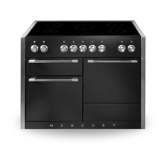
Page 11: Cooker Overview
Cooker Overview DocAUS.020-0004 - Overview - 110DF - Elan Fig. 2.1 The 1200 induction cooker (Fig. 2.1) has the following Fig. 2.2 features: 5 induction cooking zones A control panel A glide-out grill Main multi-function oven Fan oven Storage drawer The Hob Use only pans that are suitable for induction hobs. - Page 12 The very best pans have bases that are very slightly curved Fig. 2.3 up when cold (Fig. 2.3). If you hold a ruler across the bottom you will see a small gap in the middle. When they heat up the metal expands and lies flat on the cooking surface.
- Page 13 Automatic Heat-up, A Auomatic Heat-up Time at Power level 100% (min:sec) This function is available on all of the cooking zones. It allows rapid heating up of the element to bring the selected 0:48 cooking zone up to temperature. Once the zone is at the 2:24 required cooking temperature the power level will reduce 3:50...
- Page 14 The maximum time this setting can be used is 2 hours. To Fig. 2.8 increase the heat, just turn the control knob to the required A & B linked D & E linked level. Power Boost Setting, P All of the induction cooking zones have Power Boost available, activated by turning the control knob clockwise until [P ] is shown on the hob control display.
- Page 15 The Glide-out Grill Fig. 2.9 CAUTION: Accessible parts may be hot when the grill is in use. Young children should be kept away. CAUTION: This appliance is for cooking purposes only. It must not be used for other purposes, for example room heating.
-
Page 16: The Ovens
The Ovens Fan Oven This function operates the fan and the heating References to ‘left-hand’ and ‘right-hand’ ovens apply as element around it. An even heat is produced viewed from the front of the appliance. throughout the oven, allowing you to cook large The left-hand oven is a multi-function oven, while the right- amounts quickly. - Page 17 The exposed top element may cook some foods too quickly, Function so we recommend that the food be positioned in the lower half of the oven to cook. The oven temperature may also need Defrost To thaw small items in the oven without heat to be lowered.
-
Page 18: Accessories
Accessories Fig. 2.16 Fig. 2.17 Oven Shelves The cooker is supplied with the following: • 3 standard shelves (Fig. 2.16) • 1 drop shelf (Fig. 2.17) • 1 telescopic shelf with runners (Fig. 2.18) • 2 sets of side supports (Fig. 2.19) Fig. -
Page 19: Storage
To Remove and Fit a Shelf to the Side Supports Fig. 2.24 Fig. 2.25 The shelf has a small kink on either side (Fig. 2.23). To remove the shelf, line these up with the stops in the shelf support (Fig. 2.24). Lift the rear of the shelf upward so that it will pass over the shelf stop and then pull it forward (Fig. -
Page 20: Cooking Tips
Cooking Tips Cooking with a Multifunction Oven General Oven Tips Remember: not all modes are suitable for all food types. The The wire shelves should always be pushed firmly to the back oven cooking times given are intended for a guide only. of the oven. -
Page 21: Cooking Table
Cooking Table DocNo.031-0004 - Cooking table - electric & fan single cavity The oven control settings and cooking times given in the table below are intended to be used Top (T) AS A GUIDE ONLY. Individual tastes may require the temperature to be altered to provide a preferred result. -
Page 22: Cleaning Your Cooker
Cleaning Your Cooker Isolate the electricity supply before carrying out any major Fig. 5.1 cleaning. Allow the cooker to cool. Never use paint solvents, washing soda, caustic cleaners, biological powders, bleach, chlorine based bleach cleaners, coarse abrasives or salt. Do not mix different cleaning products – they may react together with hazardous results. -
Page 23: Glide-Out Grill
Glide-out Grill Fig. 5.2 Before you remove any of the grill parts for cleaning. make sure that they are cool, or use oven gloves. The grill pan and grill tray assembly can be easily removed for cleaning. Wash the grill pan and trivet washed in hot soapy water, or using our recommended Rangemaster cleaning solution. -
Page 24: Ovens
Ovens Fig. 5.6 Fig. 5.7 Base Tray The ovens have a removable base tray, which can be easily removed for cleaning. Wash the base tray with a proprietary enamel cleaner, or using our recommended Rangemaster cleaning solution. Alternatively, wash the base tray in a dishwasher. ‘Cook &... -
Page 25: Cleaning Table
Cleaning Table Cleaners listed (Table 5.1) are available from supermarkets or electrical retailers as stated. For enamelled surfaces use a cleaner that is approved for use on vitreous enamel. Regular cleaning is recommended. For easier cleaning, wipe up any spillages immediately. Hotplate Part Finish... -
Page 26: Troubleshooting
Troubleshooting DocNo.050-0001 - Troubleshooting - Induction GENERIC Interference with and repairs to the hob MUST NOT The cooling fan be carried out by unqualified persons. Do not try The induction hob incorporates a cooling fan. This cooling to repair the hob as this may result in injury and fan is active when either the grill or the oven(s) are on. - Page 27 Food is cooking too slowly, too quickly, or burning Fig. 6.1 Cooking times may differ from your previous oven. Check that you are using the recommended temperatures and shelf positions – see the oven cooking guide. Individual tastes may ArtNo.324-0005 Oven light bulb require the temperature to be altered either way, to get the results you want.
-
Page 28: Installation
INSTALLATION Check the appliance is electrically safe when you have finished. Installation Dear Installer Location of Cooker Before you start your installation, please complete the details The cooker may be installed in a kitchen/kitchen diner but NOT in a room containing a bath or shower. below, so that, if your customer has a problem relating to your installation, they will be able to contact you easily. -
Page 29: Positioning The Cooker
90 mm minimum A clearance of 90 mm is required if the cooker is near a corner ArtNo.110-0081 - 120 IN - Mercury door clearances of the kitchen to allow the oven doors to open (Fig. 7.3). The actual opening of the doors is slightly less but this allows for Fig. -
Page 30: Fitting The Flue, Flue Vent And Side Panels
INSTALLATION Check the appliance is electrically safe when you have finished. Fitting the Flue, Flue Vent and Side Panels Fitting the Flue Checking the Parts: Remove the four screws from the grill flue opening (Fig. Flue Flue Vent 8.1). Present the removable flue up to grill flue opening. Make sure that the bottom flange of the removable flue fits inside the fixed flue, secure in place with the four screws (Fig. -
Page 31: Fitting The Side Panel Rear Retaining Brackets
INSTALLATION Check the appliance is electrically safe when you have finished. Fitting the Side Panel Rear Checking the Parts: Retaining Brackets Side panel rear retaining brackets Side panels A052064 - Right-hand A051761 - Right-hand Located at the bottom left and right rear corner of the A052067 - Left-hand A051759 - Left-hand cooker, remove the two screws (Fig. -
Page 32: Remove The Transit Brackets
INSTALLATION Check the appliance is electrically safe when you have finished. Remove the Transit Brackets Fig. 8.6 Loosen the two screws in the underside of the transit bracket (Fig. 8.6). Slide the bracket forwards and remove. Discard the Transit Bracket. Fitting the Obscuring Trims Located near the front on each side of the cooker there are three screws. -
Page 33: Fitting The Side Panels
INSTALLATION Check the appliance is electrically safe when you have finished. Fitting the Side Panels Fig. 8.8 Loosen the screw in the flue vent (Fig. 8.8). Inside the top of the side panel top are two tabs. Connect these tabs into the cut-outs in the top edge of the cooker (Fig. -
Page 34: Fitting The Front Mounting Brackets
INSTALLATION Check the appliance is electrically safe when you have finished. Fitting the Front Mounting Fig. 8.11 Brackets Open the left-hand oven door and pull the drawer out to its furthest point. Push the ends of the plastic clips (Fig. 8.11 and Fig. 8.12) to release the catches holding the drawer to the side runners. -
Page 35: Fitting The Bottom Panel (Plinth)
INSTALLATION Check the appliance is electrically safe when you have finished. Fitting the Bottom Panel (Plinth) Fig. 8.15 Side panel Tilt the bottom of the panel slightly to locate the lower Bottom panel slots onto the washers (Fig. 8.15). Now rotate the panel to fit over the pins (Fig. -
Page 36: Fitting The Drawer
INSTALLATION Check the appliance is electrically safe when you have finished. Fitting the Drawer Fig. 8.19 To fit the drawer, pull the side rails fully out (Fig. 8.19). Carefully move the drawer back between the rails and rest it on the side rails. At each side, hold the front of the drawer and pull the side rail forward so that the clips click into position, holding the drawer to the side rails (Fig. -
Page 37: Removing The Side Panels
INSTALLATION Check the appliance is electrically safe when you have finished. Removing the Side Panels You will need the following equipment to remove the side Fig. 9.1 panels: Cross-head screwdriver Flat head screwdriver Allen keys (provided in pack). Removing the Storage Drawer Pull the drawer out to its furthest point. - Page 38 INSTALLATION Check the appliance is electrically safe when you have finished. Removing the Side Panels Fig. 9.5 Loosen one screw in the vent (Fig. 9.5). Push forward the side panel so that it moves away from the flue vent and the retaining washer (Fig. 9.6). Inside the top of the side panel top are two tabs.
-
Page 39: 10. Electrical Connection
INSTALLATION Check the appliance is electrically safe when you have finished. 10. Electrical Connection The cooker must be installed by a qualified electrician, in Current Operated Earth Leakage Breakers accordance with all relevant British Standards/Codes of The combined use of your cooker and other domestic Practice (in particular BS 7671), or with the relevant national appliances may cause nuisance tripping, so we recommend and local regulations. -
Page 40: 11. Circuit Diagrams
11. Circuit Diagrams Earth Induction unit Hob display ArtNo.083-0013 - IN 1200 - Circuit diagram - Mercury L(1) L(2) L(3) N4 w/br Interface w/br w/br board w/br w/br Code Description Code Colour w/br Left-hand front element White or brown Left-hand back element... - Page 41 Oven P095199 P095199 P095199 P028728 The connections shown in the circuit diagram are for single-phase. The ratings are for 230 V 50 Hz. Code Description Code Description Code Colour Left-hand MF oven control Right-hand fan oven control switch Blue Left-hand MF oven control switch Right-hand fan oven thermostat Brown Left-hand MF oven thermostat...
-
Page 42: 12. Technical Data
COUNTRY OF DESTINATION: GB, IE, FR, NL, DE, SE, BE, AT, CH, LU. Connections Electric 230 / 400 V ~ 50 Hz 3N Dimensions Model Mercury 1200 Induction Overall height minimum 920 mm maximum 945 mm Overall width 1190 mm... - Page 43 Hotplate Efficiency Data Brand Mercury Model Identification 1200 Induction Size 1200 Type Induction Type of Hob Induction Number of electric zones Zone 1 - Ø cm 15.5 Heating Technology Energy Consumption (ECElectric cooking) - Wh/kg Zone 2 - Ø cm 18.5...
- Page 44 Oven Data Brand Mercury Model identification 1200 Induction Type of oven Electric Mass Number of cavities Left-hand Efficiency Fuel type Electric Cavity type Multifunction Power - conventional Power - forced air convection Volume Litres Energy consumption (electricity) - conventional kWh / cycle...
- Page 45 Note...
- Page 46 Note...
- Page 47 Note...
- Page 48 Clarence Street, Royal Leamington Spa, Warwickshire, CV31 2AD, England. Tel: +44 (0) 1926 457628 E-mail: consumer@mercuryappliances.co.uk...
Need help?
Do you have a question about the 1200 Induction and is the answer not in the manual?
Questions and answers