Mercury 1000 Manual
User guide & installation instructions
Hide thumbs
Also See for 1000:
- User's manual & installation instructions (36 pages) ,
- User's manual & installation instructions (48 pages) ,
- User's manual & installation instructions (48 pages)
Table of Contents
Advertisement
Quick Links
Advertisement
Table of Contents

Subscribe to Our Youtube Channel
Related Manuals for Mercury 1000


Summary of Contents for Mercury 1000
- Page 1 USER GUIDE & INSTALLATION INSTRUCTIONS 1000 Mercury Dual Fuel U110086 - 12a...
-
Page 3: Table Of Contents
Contents Before You Start... Troubleshooting Personal Safety Installation Electrical Connection Safety Dear Installer Gas Connection Safety Safety Requirements and Regulations If You Smell Gas Provision of Ventilation Peculiar Smells Location of Cooker Cooling Fan Conversion Ventilation Positioning the Cooker Maintenance Moving the Cooker Oven Care Fitting the Flue, Flue Vent... -
Page 5: Before You Start
Before You Start... Your cooker should give you many years of and will retain heat even after you have trouble-free cooking if installed and operated stopped cooking. Care should be taken to correctly. It is important that you read this avoid touching heating elements. -
Page 6: Gas Connection Safety
WARNING: THE APPLIANCE MUST BE Fig. 1.1 EARTHED. Note: The cooker must be connected to the correct electrical supply as stated on the voltage label on the cooker, through a suitable cooker control unit incorporating a double- 10 mm² max pole switch, having a contact separation of at least 3 mm in all poles. -
Page 7: If You Smell Gas
In your own interest and that of safety, it is minutes with the grill pan in position, pushed • law that all gas appliances be installed by a fully back and the grill door open. qualified person(s). Make sure the room is well ventilated to the outside air (see ‘Ventilation’... -
Page 8: Oven Care
DO NOT use hotplate protectors, foil or cause spill over when food is added. If you • hotplate covers of any description. These use a combination of oils or fats in frying, may affect the safe use of your hotplate stir them together before heating, or as the burners and are potentially hazardous to fats melt. -
Page 9: Oven Shelves
The inside door face is constructed with • Fig. 1.3 toughened safety glass. Take care NOT to scratch the surface when cleaning the glass panel. Accidental damage may cause the door • ArtNo.324-0001 Steam burst glass panel to fracture. Keep oven vent ducts unobstructed. •... -
Page 10: Grill/Glide-Out Grill™ Care
NEVER use paint solvents, washing soda, Grill/Glide-out Grill™ Care • caustic cleaners, biological powders, WARNING: UNATTENDED COOKING bleach, chlorine based bleach cleaners, UNDER THE GRILL CAN BE DANGEROUS coarse abrasives or salt. AND MAY RESULT IN FIRE. DO NOT mix different cleaning products •... -
Page 11: Cooker Overview
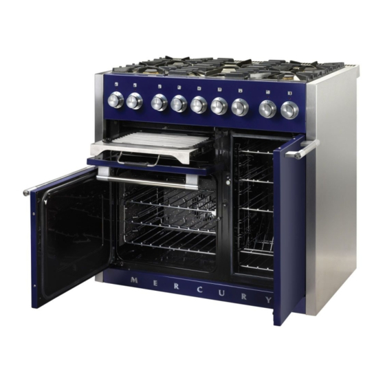
DocAUS.020-0004 - Overview - 110DF - Elan Cooker Overview Fig. 2.1 The 1000 dual fuel cooker (Fig. 2.1) has the following Fig. 2.2 features: 5 hotplate burners including 1 wok burner A control panel A glide-out grill Main multifunction oven... -
Page 12: Wok Burner
Adjust the flame height to suit by turning the knob counter- Fig. 2.3 clockwise (Fig. 2.3). On this cooker the low position is beyond high, not between high and off. If a burner flame goes out, turn off the control knob and leave it for one minute before relighting it. -
Page 13: The Glide-Out Grill™ (Fig. 2.13)
DO NOT put it crossways – it will not fit properly and Fig. 2.11 will be unstable (Fig. 2.12). DO NOT put it on any other burners – it is not designed to fit in any of the other pan supports. Position the griddle over the hotplate burners resting on the pan support. -
Page 14: Ovens
amounts quickly. Ovens Fan oven cooking is particularly suitable for baking on several References to ‘left-hand’ and ‘right-hand’ ovens apply as shelves at one time and is a good ‘all-round’ function. It may viewed from the front of the appliance. be necessary to reduce the temperature by approximately The left-hand oven is a multifunction oven, while the right- 10 °C for recipes previously cooked in a conventional oven. - Page 15 Browning Element Function This function uses the element in the top of the oven Defrost To thaw small items in the oven without heat only. It is a useful function for the browning or finishing of pasta dishes, vegetables in sauce, A full cooking function, even heat throughout, Fan oven shepherds pie and lasagne, the item to be browned being...
-
Page 16: Accessories
Accessories Fig. 2.18 Fig. 2.19 Oven Shelves The cooker is supplied with the following: Left-hand Oven • 1 standard shelf (Fig. 2.18) • 1 drop shelf (Fig. 2.19) • 1 telescopic shelf with runners (Fig. 2.20) Fig. 2.20 Fig. 2.21 •... - Page 17 The shelf has a small kink on either side (Fig. 2.28). To remove Fig. 2.25 the shelf, line these up with the stops in the shelf support (Fig. 2.29). Lift the rear of the shelf upward so that it will pass over the shelf stop and then pull it forward (Fig.
-
Page 18: Using The Glide-Out Grill
DocAUS.020-0004 - Overview - 110DF - Elan Using the Glide-out Grill™ Fig. 3.2 Fig. 3.1 Nearest to the element Middle High Middle Low Furthest from the element Four grill height positions refer to Fig. 3.5 Fig. 3.4 Fig. 3.3 To switch on both elements To switch on the right half element Four grill height positions Fig. -
Page 19: Cooking Tips
Cooking Tips Cooking with a Multifunction Oven General Oven Tips Remember: not all modes are suitable for all food types. The The wire shelves should always be pushed firmly to the back oven cooking times given are intended for a guide only. of the oven. -
Page 20: Cooking Table
DocNo.031-0004 - Cooking table - electric & fan single cavity Cooking table The oven control settings and cooking times given in the table below are intended to be used Top (T) AS A GUIDE ONLY. Individual tastes may require the temperature to be altered to provide a ArtNo.050-0007 preferred result. -
Page 21: Cleaning Your Cooker
Cleaning Your Cooker Essential Information Fig. 6.1 Isolate the electricity supply before carrying out any thorough cleaning. Allow the cooker to cool. ArtNo.311-0028 - Burner head off NEVER use paint solvents, washing soda, caustic cleaners, biological powders, bleach, chlorine based bleach cleaners, coarse abrasives or salt. -
Page 22: Griddle (Optional Extra)
Wipe loose debris from main top. Avoid using any abrasive Fig. 6.4 cleaners including cream cleaners. For best results use a liquid detergent cleaner. Rinse with cold water and thoroughly dry with a clean, soft cloth. Ensure all parts are dry before repositioning. Griddle (Optional Extra) Always clean the griddle after use. -
Page 23: Control Panel And Oven Doors
Control Panel and Oven Doors Fig. 6.8 Avoid using any abrasive cleaners including cream cleaners. For best results, use a liquid detergent. The control panel and control knobs should only be cleaned with a soft cloth wrung out in clean hot soapy water – but take care that no surplus water seeps into the appliance. -
Page 24: Cleaning Table
Cleaning Table Cleaners listed (Table 6.1) are available from supermarkets or electrical retailers as stated. For enamelled surfaces use a cleaner that is approved for use on vitreous enamel. Regular cleaning is recommended. For easier cleaning, wipe up any spillages immediately. Hotplate Part Finish... -
Page 25: Troubleshooting
Troubleshooting Hotplate/Cooktop ignition or hotplate burners faulty Food is cooking too slowly, too quickly, or burning Is the power on? If not, there maybe something wrong with Cooking times may differ from your previous oven. the power supply. Check that you are using the recommended temperatures Are the sparker (ignition electrode) or burner slots blocked by and shelf positions –... - Page 26 The left-hand oven door is misaligned Fig. 7.1 Fig. 7.2 The bottom hinge of the left-hand oven door can be adjusted to alter its angle (Fig. 7.3). Loosen the bottom hinge fixing screws and use the notch and a flat bladed screwdriver to move the position of the hinge to set the hinge position (Fig.
-
Page 27: Installation
INSTALLATION Check the appliance is electrically safe when you have finished. Installation In the UK the cooker must be installed in accordance Dear Installer with: Before you start your installation, please complete the details • All relevant British Standards / Codes of Practice, in below, so that, if your customer has a problem relating to particular BS 5440 Part 2. -
Page 28: Location Of Cooker
INSTALLATION Check the appliance is electrically safe when you have finished. Location of Cooker Checking the Parts: The cooker may be installed in a kitchen/kitchen diner but 5 pan supports Wok cradle NOT in a room containing a bath or shower. This appliance is designed for domestic cooking only. -
Page 29: Positioning The Cooker
65 °C above room temperature. We recommend a gap of 1000 mm between units to allow for moving the cooker. Do not box the cooker in – it must be possible to move the cooker in and out for cleaning and servicing. -
Page 30: Fitting The Flue, Flue Vent And Side Panels
INSTALLATION Check the appliance is electrically safe when you have finished. Fitting the Flue, Flue Vent and Side Panels Fitting the Flue Checking the Parts: Remove the four screws from the grill flue opening (Fig. Flue Flue Vent 9.1). Present the removable flue up to grill flue opening. Make sure that the bottom flange of the removable flue fits inside the fixed flue, secure in place with the four screws (Fig. -
Page 31: Fitting The Side Panel Rear Retaining Brackets
INSTALLATION Check the appliance is electrically safe when you have finished. Fitting the Side Panel Rear Checking the Parts: Retaining Brackets Side panel rear retaining brackets Side panels A052064 - Right-hand A051761 - Right-hand Located at the bottom left and right rear corner of the A052067 - Left-hand A051759 - Left-hand cooker, remove the two screws (Fig. -
Page 32: Remove The Transit Brackets
INSTALLATION Check the appliance is electrically safe when you have finished. Remove the Transit Brackets Fig. 9.6 Loosen the two screws in the underside of the transit bracket (Fig. 9.6). Slide the bracket forwards and remove. Discard the Transit Bracket. Fitting the Obscuring Trims Located near the front on each side of the cooker there are three screws. -
Page 33: Fitting The Side Panels
INSTALLATION Check the appliance is electrically safe when you have finished. Fitting the Side Panels Fig. 9.8 Loosen the screw in the flue vent (Fig. 9.8). Inside the top of the side panel top are two tabs. Connect these tabs into the cut-outs in the top edge of the cooker (Fig. -
Page 34: Fitting The Front Mounting Brackets
INSTALLATION Check the appliance is electrically safe when you have finished. Fitting the Front Mounting Fig. 9.13 Brackets Left Mounting Open the left and right-hand oven door Plate On the front of the cooker base there are two mounting plates. Remove the three fixing screws from each plate (Fig. -
Page 35: Completing The Move
INSTALLATION Check the appliance is electrically safe when you have finished. Completing the Move Fig. 9.15 Open the grill door and right-hand oven door so that you can get a good grip on the bottom of the fascia panel as you move the oven (Fig. -
Page 36: 10. Removing The Side Panels
INSTALLATION Check the appliance is electrically safe when you have finished. 10. Removing the Side Panels You will need the following equipment to remove the side Fig. 10.1 panels: Cross-head screwdriver Flat head screwdriver Allen keys (provided in pack). Removing the Bottom Panel (Plinth) Open the left and right-hand oven door Unscrew the two allen head screws (Fig. - Page 37 INSTALLATION Check the appliance is electrically safe when you have finished. Removing the Side Panels Fig. 10.3 Loosen one screw in the vent (Fig. 10.3). Push forward the side panel so that it moves away from the flue vent and the retaining washer (Fig. 10.4). Inside the top of the side panel top are two tabs.
-
Page 38: 11. Conversion To Lp Gas
WARNING – SERVICING TO BE CARRIED OUT ONLY BY AN AUTHORISED PERSON Disconnect from electricity and gas before servicing. Check appliance is safe when you have finished. 11. Conversion to LP Gas Check the ‘Technical Data’ section at the back of the book Fig. -
Page 39: Tap Adjustment
WARNING – SERVICING TO BE CARRIED OUT ONLY BY AN AUTHORISED PERSON Disconnect from electricity and gas before servicing. Check appliance is safe when you have finished. Note: When refitting the hotplate, take care not to damage or Fig. 11.5 displace the flame safety probes (Fig. -
Page 40: 12. Gas Connection
INSTALLATION Check the appliance is electrically safe and gas sound when you have finished. 12. Gas Connection Gas Connection Fig. 12.1 This must be in accordance with the relevant standards. Pipework Pipework The flexible hose (not supplied with the cooker) must be in accordance with the relevant standards. -
Page 41: 13. Electrical Connection
INSTALLATION Check the appliance is electrically safe and gas sound when you have finished. 13. Electrical connection The cooker must be installed by a qualified electrician, in Current Operated Earth Leakage Breakers accordance with all relevant British Standards/Codes of The combined use of your cooker and other domestic Practice (in particular BS 7671), or with the relevant national appliances may cause nuisance tripping, so we recommend and local regulations. -
Page 42: 14. Circuit Diagram
14. Circuit Diagram P095199 P095199 P028728 B2 B3 br b The connections shown in the circuit diagram are for single-phase. The ratings are for 230 V 50 Hz. Code Description Code Description Code Colour Left-hand multi-function oven control Right-hand fan oven control Blue Left-hand multi-function oven control switch Right-hand fan oven thermostat... -
Page 43: 15. Technical Data
29 mbar 230/400 V 50 Hz Propane 37 mbar See the appliance badge for test pressures. Dimensions Model Mercury 1000 Dual Fuel Overall height minimum 920 mm maximum 945 mm Overall width 990 mm Overall depth 638 mm excluding handles, 700 mm including handles... - Page 44 700 DEPTH INCLUDING HANDLE 638 DEPTH EXCLUDING HANDLE...
- Page 45 Hotplate Efficiency Data Brand Mercury Model Identification 1000 DF Size 1000 Type Dual Fuel Type of Hob Number of gas burners Auxiliary / Small Burner (EE gas burner) Semi Rapide / Medium Burner (EE gas burner) 60.8% Semi Rapide / Medium Burner (EE gas burner) Rapide / Large Burner (EE gas burner) 58.5%...
- Page 46 Oven Data Brand Mercury Model identification 1000 DF Type of oven Electric Mass Number of cavities Left-hand Efficiency Fuel type Electric Cavity type Multifunction Power - conventional Power - forced air convection Volume Litres Energy consumption (electricity) - conventional kWh / cycle 0.96...
- Page 47 NOTE...
- Page 48 Clarence Street, Royal Leamington Spa, Warwickshire, CV31 2AD, England. Tel: +44 (0) 1926 457628 E-mail: consumer@mercuryappliances.co.uk...
Need help?
Do you have a question about the 1000 and is the answer not in the manual?
Questions and answers