Table of Contents
Advertisement
Quick Links
2060 Cessna Dr, Suite 100
Vacaville, CA 95688
telephone: 707-448-5151
fax: 707-448-1521
www.bloomfieldworldwide.com
Includes:
Installation
Use & Care
Servicing Instructions
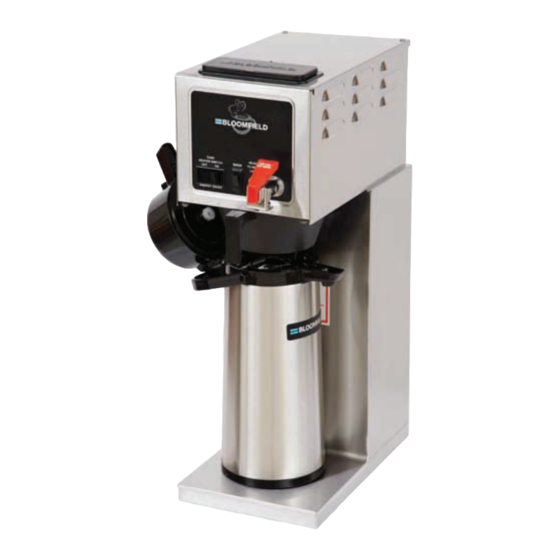
Model 8773 Brewer
with optional
7760 Airpot
76451
p/n 2M-
R
e
. v
G
OWNERS MANUAL
INTEGRITY™
COFFEE BREWERS
MODELS
8773 Automatic Airpot Brewer
8774 Pour-Over Airpot Brewer
Domestic and
Export Models
Model 8774 Brewer
with optional
8881 Airpot
603
For
21
M
6
0
3
0505
Advertisement
Table of Contents

Related Manuals for Bloomfield WUNDER-BAR INTEGRITY 8773


Summary of Contents for Bloomfield WUNDER-BAR INTEGRITY 8773
- Page 1 OWNERS MANUAL 2060 Cessna Dr, Suite 100 Vacaville, CA 95688 telephone: 707-448-5151 INTEGRITY™ fax: 707-448-1521 www.bloomfieldworldwide.com COFFEE BREWERS Includes: MODELS Installation 8773 Automatic Airpot Brewer Use & Care 8774 Pour-Over Airpot Brewer Servicing Instructions Domestic and Export Models Model 8773 Brewer Model 8774 Brewer with optional with optional...
- Page 2 WARRANTY STATEMENT All electrical equipment manufactured by BLOOMFIELD is warranted against defects in materials and workmanship upon the limitations in this warranty. Seller’s obligation under for a period of (1 year labor, two year parts) from the date this warranty is limited to the repair of defects without charge...
-
Page 3: Table Of Contents
TABLE OF CONTENTS WARRANTY STATEMENT Thank You for purchasing this SPECIFICATIONS FEATURES & OPERATING CONTROLS PRECAUTIONS & GENERAL INFORMATION AGENCY LISTING INFORMATION INSTALLATION INSTRUCTIONS OPERATION BREWING COFFEE CLEANING INSTRUCTIONS TROUBLESHOOTING SUGGESTIONS SERVICING INSTRUCTIONS EXPLODED VIEWS & PARTS LISTS SERVICE KITS WIRING DIAGRAMS SPECIFICATIONS... -
Page 4: Features & Operating Controls
FEATURES AND OPERATING CONTROLS IL1626 Fig. 1 Features & Operating Controls... -
Page 5: Precautions & General Information
PRECAUTIONS AND GENERAL INFORMATION WARNING: ELECTRIC SHOCK HAZARD WARNING service personnel. Do not open any access panels which require the use of tools. Failure to heed this warning can result in electrical shock. WARNING: INJURY HAZARD WARNING all applicable electrical and plumbing codes. Failure could result in property damage and personal injury. -
Page 6: Installation Instructions
INSTALLATION INSTRUCTIONS READ THIS CAREFULLY BEFORE STARTING THE INSTALLATION CAUTION: Unpack the unit. Inspect all components for completeness and EQUIPMENT DAMAGE condition. Ensure that all packing materials have been removed from the unit. DO NOT plug in or energize this DO NOT pl Verify that the Spray Head Gasket and Spray Disk are properly appliance until all Installation... - Page 7 INSTALLATION INSTRUCTIONS (continued) WARNING: SHOCK HAZARD Brewer must be properly Brewer mu grounded to prevent possible shock hazard. DO NOT assume a plumbing line IL1596 will provide such a ground. Fig. 2 Water Supply Installation - New-Style Brewers Electrical shock will cause death or serious injury.
-
Page 8: Operation
OPERATION IL1627 Fig. 3 Model 8773 Operation Diagram IMPORTANT: START-UP Tank must be full of For initial start-up, or if the brewer has not been used for an water before connecting extended period of time: brewer to electrical power. Heating elements will be Be sure spray disk and brew gasket are properly installed in the damaged if allowed to brew head. - Page 9 OPERATION (continued) WATER HEATER Water temperature is sensed by a thermobulb inserted into the water tank. This temperature signal is fed to the thermostat, which controls line power to the heating element. The setpoint temperature is adjustable at the thermostat. The element is protected from over-tempera- ture by a hi-limit thermostat.
-
Page 10: Brewing Coffee
BREWING COFFEE CAUTION: A. PREPARATION BURN HAZARD PAPER FILTER Exposed surfaces Add a pre-measured amount of of the brewer, brew cham- fresh coffee grounds. ber and airpot may be BREW Gently shake the brew chamber to CHAMBER HOT to the touch, and can level the bed of grounds. -
Page 11: Cleaning Instructions
CLEANING INSTRUCTIONS PROCEDURE: Clean Coffee Brewer CAUTION: PRECAUTIONS: Disconnect brewer from electric power. BURN HAZARD Allow brewer to cool. Brewing and serving Brewing a FREQUENCY: Daily temperatures of coffee are extremely hot. TOOLS: Mild Detergent, Clean Soft Cloth or Sponge Hot coffee will cause Bristle Brush, Bottle Brush serious skin burns. -
Page 12: Troubleshooting Suggestions
TROUBLESHOOTING SUGGESTIONS SYMPTOM POSSIBLE CAUSE SUGGESTED REMEDY Brewer unplugged or circuit breaker Check power supply cord Check / tripped reset circuit breaker Thermostat set too low Set for desired temperature Allow to cool, Reset hi-limit (8786, Hi-Limit thermostat tripped Water won’t heat (be sure TANK 8788) HEAT switch is ON) Examine wiring &... -
Page 13: Servicing Instructions
SERVICING INSTRUCTIONS ACCESS PANELS CAUTION: SHOCK HAZARD TOP PANEL: Remove top panel to access hot water tank, thermostat, heating Opening access panels or Opening acc elements, brew circuit tubing, faucet valve and piping. removing warmer plates on this Top panel is held by two screws at the rear and a retaining lip at brew may expose uninsulated the front. - Page 14 SERVICING INSTRUCTIONS (continued) TEMPERATURE ADJUSTMENT CAUTION: SHOCK HAZARD Unplug power cord or turn circuit breaker OFF. Remove top panel. These procedures involve These proc These proc exposed electrical circuits. Pull vent tube out of tank lid and insert a thermometer of known These procedures are to accuracy in vent hole.
- Page 15 SERVICING INSTRUCTIONS (continued) TIMER ADJUSTMENT (AUTOMATIC BREWERS ONLY) IMPORTANT: Water pressure must be between 20 p.s.i and If water pressure exceeds this Place empty decanter under brew chamber. Press BREW r. T y, a pressure the water supply line. REMOVE TANK LID ASSEMBLY OFF.
- Page 16 SERVICING INSTRUCTIONS (continued) REPLACE HEATING ELEMENT IMPORTANT: Remove tank lid assembly per above. When replacing heating element, also replace seal gaskets. Remove two hex nuts holding element to cover. Pull element from mounting holes. Reassemble in reverse order. REPLACE SOLENOID Symptom: automatic brewer drips continuously from brew head.
- Page 17 SERVICING INSTRUCTIONS (continued) REPLACE TIMER ASSEMBLY timer to bracket. Disconnect wiring to timer. REPLACE HOT WATER FAUCET COIL IMPORTANT: When replacing water faucet coil, also replace seal gaskets. r. Pull coil from mounting holes. REPAIR HOT WATER FAUCET faucet shut-of NOTE: Any abrasion or seat cup will require replacing the seat cup:...
- Page 18 SERVICING INSTRUCTIONS (continued) CAUTION: AUTION: PROCEDURE: Delime the Water Tank PROCEDURE: Delime the Water Tank CHEMICAL BURN HAZARD PRECAUTIONS: Disconnect brewer from electric power. Deliming chemicals may be Deliming ch Allow brewer to cool. caustic. Wear appropriate protective gloves and goggles FREQUENCY: As required (Brewer slow to heat) during this procedure.
- Page 19 SERVICING INSTRUCTIONS (continued) 7. Set the tank back into the brewer. Reassemble the tank lid to Set the tank back into the brewer Reassemble the tank lid to NOTE: Normally, silicone hoses NOTE: Normally silicone hoses the water tank. Make sure the gasket is properly in place, do not need to be delimed.
-
Page 20: Exploded Views & Parts Lists
EXPLODED VIEW & PARTS LIST HOT WATER TANK ASSEMBLY IL1630 WS-8512-51 THERMOSTAT (BLACK BODY - INCL. SEAL & MOUNTING SCREWS) 8773, 8774 WS-86280 THERMO (ALT) (GRAY BODY - INCL. TUBE & MOUNTING SCREWS) 7 - I - 2 / 7 - I 2C-70151 NUT HEX 7/16-20 BRASS 2K-Z18254... - Page 21 EXPLODED VIEW & PARTS LIST (continued) CABINET PLUMBING COMPONENTS IL1631 L ” F ” B ” L ” 2C-70107 LOCK WASHER 7/16” EXT SEMS (FAUCET) 2C-72681 WASHER, FLAT 15/32” x 1-1/8” x 1/16” SS WS-82556 FAUCET ASSEMBLY, PRESSURE 2I-70139 GASKET, SPRAY HEAD A6-72727 SPRAY DISK, EMBOSSED A6-70163...
- Page 22 EXPLODED VIEW & PARTS LIST (continued) ELECTRICAL COMPONENTS IL1632 & 2P-70128 TIMER, 2-MINUTE (WITH DIAL & KNOB) 120V 8773 (US & Canada) 2E-70353 POWER CORD ASSEMBLY, 120V NEMA 5-15P 8773, 8774 (US & Canada) & & & WS-8512-51 THERMOSTAT (BLACK BODY - INCL. SEAL & MOUNTING SCREWS) 8773, 8774 WS-86280 THERMO (ALT) (GRAY BODY - INCL.
- Page 23 EXPLODED VIEW & PARTS LIST (continued) CABINET COMPONENTS IL1633a ITEM PART NO. DESCRIPTION USED ON 2I-70139 GASKET, SPRAY HEAD 8773, 8774 A6-72727 SPRAY DISK, EMBOSSED 8773, 8774 A6-70163 RETAINER, SPRAY HEAD (REQUIRES DRILL/RIVETS TO INSTALL) 8773, 8774 2P-70053 BUTTON PLUG, 2”, METAL 8773, 8774 2A-71732 LEG ASSEMBLY, LEVELLING...
-
Page 24: Service Kits
SERVICE KITS SOLENOID REPAIR KITS 85218 Inlet Fitting Kit (items 45a, 45b, 45c, 45d) 85219 Inlet Strainer (item 45d) IL1612 COMPLETE SPARE TANK COVER WS-8541 WF-300 Spare Cover Assembly (120V, 1500W, 8773 (U.S. & Canada) With Coil - all parts mounted to cover) WS-8543-300 Spare Cover Assembly (120V, 1500W, 8774 (U.S. -
Page 25: Wiring Diagrams
WIRING DIAGRAMS... - Page 26 NOTES...
- Page 27 NOTES...
- Page 28 2060 Cessna Dr, Suite 100 Vacaville, CA 95688 phone (707)448-5151 fax (707)448-1521 www.bloomfieldworldwide.com...
Need help?
Do you have a question about the WUNDER-BAR INTEGRITY 8773 and is the answer not in the manual?
Questions and answers