Advertisement
Quick Links
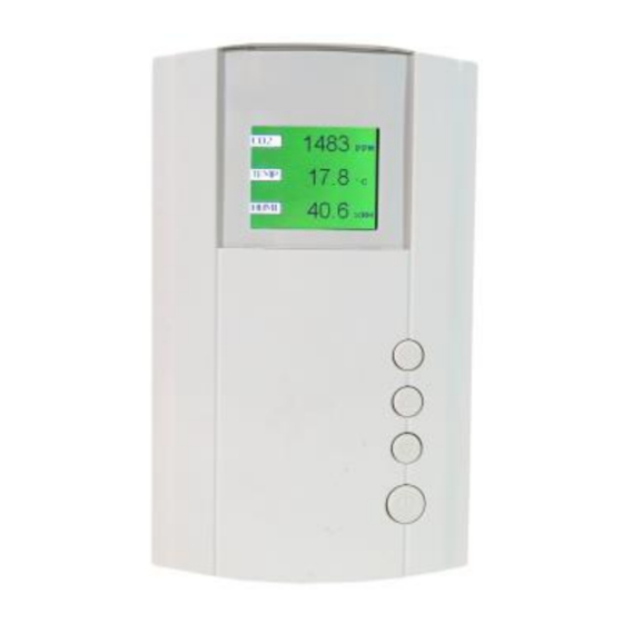
CO2/Te/RH Transmitter/Controller
Model
: AT-VLX-A1-R1-RS
Features
➢
Indoor air quality transmitter/controller
➢
Internal sensors to measure CO2 & temperature
➢
3-color TFT screen display + 3-color alarm indication
➢
Four function keys to adjust setpoints
Providing 1x analog output & 1x relay on/off output
➢
➢
Linear or PID output selectable for analog
➢
Modbus RS485 interface to connect to BMS/PLC
➢
24VAC/VDC power supply
Specification
Carbon Dioxide
Detecting gas
Gas sensor
Accuracy@25°C
Stability
Calibration
Lifetime of NDIR CO2 sensor
Response time
Sample time
Warm up time
CO2 measuring range
CO2 display resolution
Temperature
Temperature sensor (selectable)
Measuring range
Carbon Dioxide (CO2)
NDIR sensor
±50ppm + 3% reading or ±75ppm (whichever is greater)
<2% of FS over lifetime (15 years) of sensor
ABC Logic self-calibration
15 years (normal using)
<2 minutes for 90% step change
Every 2 sec
2 hours (first time or startup after power failure)
2 min (operation)
0~5000ppm (default)
0~2000ppm (selected in Advanced Setup)
1ppm
NTC thermistor
-20~60°C (default)
User Manual
1
Advertisement

Subscribe to Our Youtube Channel
Related Manuals for Atal AT-VLX-A1-R1-RS


Summary of Contents for Atal AT-VLX-A1-R1-RS
- Page 1 CO2/Te/RH Transmitter/Controller User Manual Model : AT-VLX-A1-R1-RS Features ➢ Indoor air quality transmitter/controller ➢ Internal sensors to measure CO2 & temperature ➢ 3-color TFT screen display + 3-color alarm indication ➢ Four function keys to adjust setpoints Providing 1x analog output & 1x relay on/off output ➢...
- Page 2 Accuracy <±0.5°C@25°C Electrical Specification and Functions Power supply 24VAC/VDC Power consumption 5.5 W max. ; 2.5 W avg. LCD screen 3-color TFT screen, with 4 function keys 1× analog ouotputs & 1x relay on/off output Output Analog: linear (0~10V or 4~20mA) or PID Communication interface Modbus RS485 Operation Condition...
- Page 3 Fig. 2 TFT Display & Buttons The front cover contains a TFT screen and 4 function keys: SET, ▲, ▼, and Power: be used to turn on/off the transmitter/controller. When turning off, “OFF” will be displayed on the right ➢ bottom corner, and in this situation all outputs are ineffective.
- Page 4 Linear Linear Linear Linear Linear Linear Linear Linear Linear Linear Linear Linear Linear Linear Linear Linear Linear Table 2 - Voltage output or current output selection via jumpers Jumpers S1~S6 on PCB Jumper SET on PCB Analog output terminals S1 connect V, S2 connect V SET connect lower two pins AN1=0~10V S1 connect V, S2 connect V...
-
Page 5: Advanced Setup
Function Auto control Auto control Manual control Manual control ON1- decrease CO2 ON1- increase CO2 ON1- OFF ON1 -ON For example, end user may set the CO2 relay offset by Advanced Setup parameters P16. The relay 1 auto control logic is as explained below: a. - Page 6 0.0 ~ 30.0ppm 20.0 TVOC yellow to red setpoint 1 ~ 4 (see table 4) The relay mode for CO2 1 ~ 4 (see table 5) The relay mode for Temp 1 ~ 4 (see table 6) The relay mode for Humi 1 ~ 4 (see table 7) The relay mode for TVOC 1 ~ 5000ppm...
- Page 7 CO2 PID period setpoint 0.1 ~ 10000.0 CO2 PID-P setpoint -10000 ~ 10000 -2.0 CO2 PID-I setpoint 0.0 ~ 10000.0 10.0 CO2 PID-D setpoint 0.0 ~ 10000.0 10.0 Temp PID period setpoint 0.1 ~ 10000.0 Temp PID-P setpoint -10000 ~ 10000 Temp PID-I setpoint 0.0 ~ 10000.0 10.0...
- Page 8 TVOC PID self-tuning 1- Run TVOC control PID self-tuning 0- stop PID self-tuning Power on again 1- turn off 2-turn on after power up again 3- hold the mode before the power failure Temperature unit 1- Degree Celsius; 2- Fahrenheit CO2 ABC Logic ABC Logic ON;...
- Page 9 Modbus Parameters V3.1 Mode: RTU (MSB First) Baud Rate: 9600/14400/19200/38400/56000/57600/76800/115200 bps default: 9600 Start Bits: 1 Data Bits: 8 Stop Bits: 1 / 2 default : 1 Parity: None / Odd / Even default: None Register Map Support Function: 3 4 6 16 Correspond Starting Data Description...
- Page 10 Humi. UINT16 1~100 => 1~100 RH% Measurement x 1 times TVOC UINT16 0~30 => 0~30ppm measurement x 1 times Co2 Measurement UINT16 0~5000 => 0~5000 ppm Temp. INT16 -200~600 =>-20.0~60.0℃/ Measurement -400~1400=>-40.0~140.0 ℉ x 10 times Humi. UINT16 1~1000 => 0.1~100.0 RH% Measurement x 10 times TVOC...
- Page 11 choice Temperature unit UINT16 1-Degree Celsius; P-66 selection 2-Fahrenheit AN1 AN2 AN3 UINT16 0~15 Table 3 PID or Linear output choice Co2 setpoint for 3/16 Float 0~5000ppm User “Co2 relay1 and Big-endian setpoint” AN1(0~10V/4~20 mA) PID Temp setpoint for 3/16 Float 21.0 User “Temp...
- Page 12 AN1(0~10V/4~20 mA) PID Temp setpoint for INT16 -200~600 => -20.0~60.0℃ User“Temp relay2 and setpoint” AN2(0~10V/4~20 mA) PID x 10 times Humi setpoint for UINT16 0~1000 => 0.0~100.0%RH User“Humi relay3 and setpoint” AN3(0~10V/4~20 mA) PID x 10 times TVOC setpoint for UINT16 0~300 =>...
- Page 13 AN1 CO2 linear 3/16 Float 0~5000ppm 5000 P-23 max value Big-endian 0~10.000v 10.000 P-24 AN1 CO2 linear 3/16 Float max volt Big-endian AN2 Temp linear 3/16 Float P-25 -20.0~60.0℃ -20.0 Big-endian AN2 Temp linear 3/16 Float 0~10.000v 0.000 P-26 Big-endian AN2 Temp linear 3/16 Float...
- Page 14 2-auto control relay ON3-> humidification 3-hand control relay ON3-> 4-hand control relay ON3-> P-15 the relay mode for UINT16 1-auto control relay ON3-> TVOC reduce TVOC 2-auto control relay ON3-> increase TVOC 3-hand control relay ON3-> 4-hand control relay ON3-> CO2 offset for 3/16 Float...
- Page 15 Big-endian <0 -> Temp cool >0 -> Temp heat Temp TI 3/16 Float 0.0~10000.0 40.0 P-43 Big-endian 0.0~10000.0 10.0 P-44 Temp TD 3/16 Float Big-endian Humi CYCLE 3/16 Float 0.1~10000.0 P-45 Big-endian Humi GAIN 3/16 Float P-46 -10000.0~10000.0 -2.0 Big-endian <0 ->...
- Page 16 20mA) setpoint output (MAN) P-57 Humi PID manual 3/16 Float 0-Humi control PID output AN3 choice Big-endian AN3(0~10VDC/4~20mA )o (MAN ON) utput 1-manual control AN3(0~10VDC/4~20mA) output Humi PID manual 3/16 Float 0~100% <=> P-58 output Big-endian AN3(0~10VDC/4~20mA) AN3(0~10VDC/4~ output 20mA) setpoint (MAN) TVOC PID manual 3/16...
- Page 17 (Read Only) Big-endian Temp LMN Output Float (Read Only) Big-endian Humi PID 3/16 Float 1-Start CO2 PID self-tuning P-63 self-tuning Big-endian 0-Stop CO2 PID self-tuning (TUN_ON) or CO2 PID self-tuning had finished Humi PHASE Float (Read Only) Big-endian Humi STATUS_H Float (Read Only) Big-endian...
Need help?
Do you have a question about the AT-VLX-A1-R1-RS and is the answer not in the manual?
Questions and answers