Table of Contents
Advertisement
Quick Links
Advertisement
Table of Contents

Related Manuals for Atal AT 505


Summary of Contents for Atal AT 505
- Page 1 1.11 onwards USER’S MANUAL Last updated: April 26. 2023 The right is reserved to change the Manual ATAL s.r.o., Lesní 47, 390 01 Tábor - Horky, Czech Republic Phone: +420 381 410 100 e-mail: info@atal.cz; web: http://www.atal.cz GAS_MANUAL_EN.DOC...
-
Page 2: Table Of Contents
DETECTION OF COMMUNICATION PORTS ........................................15 PROGRAM CONTROL ................................................ 16 DEVICE SWITCH-ON AND SOFTWARE START-UP ......................................16 CONNECTION OF AT 505 TO THE PERSONAL COMPUTER (MFS LIGHT) ..............................17 PROGRAM START-UP ............................................... 19 DEVICE ACTIVITIES AFTER PROGRAM START-UP ......................................19 9.3.1... -
Page 3: Chap. I - Gas Analyser
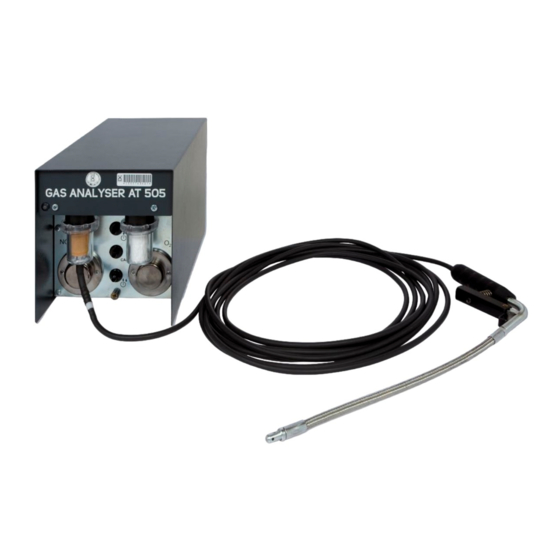
Chap. I - Gas Analyser INTRODUCTION The gas analyser is a PC based four (plus optional NOx) gas analyser. • The gas analyser is intended for the maintenance and inspection of spark ignition engines. • • Gas data is transmitted from the gas analyser to the PC (or Laptop) for processing and printing. The gas analyser is part of the modular Multi-Diag system. -
Page 4: Front Panel
Chap. I - Gas Analyser The gas analyser is a four-part (optional five-part) analyser of exhaust gases, to be used for measurement and adjustment of petrol, LPG, and CNG engines, and for controlling emissions of those engines according to relevant national regulations. -
Page 5: Back Panel
Chap. I - Gas Analyser BACK PANEL - Connector (Jack) for the power supply plug - Connector for the computer serial cable Fig. 2 – View of the back panel of the Gas Analyser CONSTRUCTION OF APPARATUS MECHANICAL PART The device frame is fabricated from steel with a zinc finish, and is coated with a two-compound acrylic paint. The device case is also fabricated from steel with a zinc protective finish, and sprayed with a wear resistant powder coated paint. -
Page 6: Measuring Principle
Chap. I - Gas Analyser Fig. 3 – Scheme of pneumatic part 1- Exhaust gas intake 10- Vacuum switch 2- Coarse filter (F1) 11- Condensate pump (P2) 3- Fine filter (F2) 12- Main pump (P1) – measured gas 4- Condensate drain outlet 13- Pressure reduction –... -
Page 7: Software Installation
Chap. I - Gas Analyser Fig. 4 – Diagram of dependency of concentrations of individual gas compounds in exhaust gases (+ rich mixture, - weak mixture) SOFTWARE INSTALLATION DESCRIPTION OF INSTALLATION CD The included CD contains all the necessary software for the use of Gas Analyser system. Insert the CD in your CD-ROM drive. - Page 8 Chap. I - Gas Analyser The following set of images comes from the installation wizard for the Windows XP operation system. The Windows Vista wizard is similar: Fig. 6 – The installation can be interrupted at any time during the setup Fig.
-
Page 9: Uninstallation (Removal) Of The Gas Analyser Program
Chap. I - Gas Analyser The installation may take several seconds. Click on “Finish” to complete the installation. The installation of drivers for the RS232-USB converter starts after its completion (see Chap. I - 2) Fig. 8 – Click on "Finish” to complete the installation 7.2.2 UNINSTALLATION (REMOVAL) OF THE GAS ANALYSER PROGRAM Note:... - Page 10 Chap. I - Gas Analyser Fig. 9 – Removing Gas Analyser program by selecting the Add or Fig. 10 – Confirm that you really want to remove the program Remove Programs in Control Panel Click on the menu item Gas Analyser – Installation – see Fig.
-
Page 11: Program Configuration
Chap. I - Gas Analyser PROGRAM CONFIGURATION In order to be able to perform the program configuration under Windows 2000/XP/Vista you need to have the administrator access rights. Before running the configuration program you should: exit the Gas Analyser program install the USB to RS 232 converter connect correctly the communication cable and power supply of the analyser. -
Page 12: Configuration Screen - Special
Chap. I - Gas Analyser - Time in minutes for the device to enter standby mode (5 to 120 minutes) - Screen resolution settings - Colour and text settings - Apply button - To save the set values in the configuration program, press this button - OK button - To save the set values and exit the configuration program, press this button 10 - Cancel button - To exit the configuration program without saving the set values, press this button 11 - Wizard button - Starts the Configuration Wizard –... -
Page 13: Program Configuration Wizard
Chap. I - Gas Analyser Fig. 20 – The configuration screen (Interface) - for enabling or disabling the usage of peripheral equipment 8.1.6 PROGRAM CONFIGURATION WIZARD The Wizard (see Fig. 16, pos. 11) starts automatically when the configuration utility is ran for the first time. Fig. - Page 14 Chap. I - Gas Analyser Fig. 25 – The detected serial number is displayed (the user can Fig. 24 – Detection of the Gas Analyser serial number (performed by change it according to the label attached at the underside of the the device) analysed) Fig.
-
Page 15: Detection Of Communication Ports
Launch the “FindPort.exe” program which can be found on the installation CD or which can be downloaded from the website www.atal.cz/download/FindPort.exe The program displays all available serial ports (see Fig. 32). Once the testing device is connected to a serial port, its description and status are displayed on the screen (see Fig. -
Page 16: Program Control
Chap. I - Gas Analyser Fig. 33 – The status of the communication ports after connection of the testing device to a computer serial port connector The status of the communication cables is as follows: green = OK red = no connection Note: Some devices are functional with only the Rx-Tx connections made (e.g. -
Page 17: Connection Of At 505 To The Personal Computer (Mfs Light)
Chap. I - Gas Analyser CONNECTION OF AT 505 TO THE PERSONAL COMPUTER (MFS LIGHT) 10.1 14.1 15.1 X1.1 13.1 10.1 X3.1 15.1 X1.2 X2.1 11.1 12.1 16.1 11.1 12.1 Fig. 36 – Connection of AT505 and accessories — 17 —... - Page 18 Chap. I - Gas Analyser Note to Fig. 36 MFS Light Stand (MFS=Multi Function Station) LCD Monitor 19” 2.1 LCD power supply cable (230V-AC) 2.2 VGA cable (analog signal D-sub) Gas Analyser Module AT505 COM1 3.1 AT505 communication cable ........... connect to AT505 Power supply adapter 4.1 Power supply cable (230V-AC) 4.2 Power supply cable (16V-DC)
-
Page 19: Program Start-Up
Chap. I - Gas Analyser PROGRAM START-UP If everything is connected and configured properly, you can start the program. The program can be started by clicking on the Gas Analyser AT505 icon on the desktop of the screen (see Fig. 35) or on the Gas Analyser AT505 item from the “Start\Programs”... -
Page 20: Optical Bench Reset
Chap. I - Gas Analyser The device will automatically create vacuum in the withdrawal system and monitor for pressure drop caused by any leaks. If the test is successful, a notification is displayed prompting the removal of the exhaust probe seal. The test takes several minutes. -
Page 21: Main Screen Description
Chap. I - Gas Analyser Note: The reset can be carried out anytime by switching to setup mode by pressing F3 (Pos.5 - Fig. 45) and then by pressing the button in Pos.1 - Fig. 46. Fig. 43 – Optical bench reset MAIN SCREEN DESCRIPTION 10.1 GAS ANALYSER ONLY AVAILABLE WITH MULTI-DIAG SCOPE... -
Page 22: Gas Analyser - Is Not Available Multi-Diag Scope
Chap. I - Gas Analyser 10.2 GAS ANALYSER - IS NOT AVAILABLE MULTI-DIAG SCOPE Fig. 45 – Initial Gas Analyser Software screen description (Multi-Diag Scope is not available) Description of the Fig. 43 and Fig. 44: - Button: Used to exit from the program - Button: Green = measurement enabled Red = standby, fault or initialisation - see the Note below by pressing this button you will switch between standby and measuring mode... -
Page 23: Engine Speed Measuring
Chap. I - Gas Analyser Fig. 46 – Setting some parameters of the program depending on Fig. 47 – Setting some parameters of the program depending on the switching peripheral equipment on or off (see Configuration in the switching peripheral equipment on or off (see Configuration in Chap. -
Page 24: Measurement Principle
Chap. I - Gas Analyser 12.1.1 MEASUREMENT PRINCIPLE The universal speed sensor performs frequency analysis of the battery voltage. The ripple waveforms added to the DC battery voltage by the alternator allow engine speed to be computed. 12.1.2 RECOMMENDATIONS It is advantageous not to have fully charged battery - switch the headlights on for a while before •... -
Page 25: Oil Temperature Sensor
Chap. I - Gas Analyser 13.1 OIL TEMPERATURE SENSOR The proper oil temperature sensor type (with correct length set) should be used. After removing oil dip stick, set the thermometer’s rubber stop (with help of the dip stick) so that the thermometer is about 20 mm deep (30 mm max.) in the oil. -
Page 26: Ignition Advance Measuring
Chap. I - Gas Analyser 1 - Tab: for ignition advance selection Note: Tab is only available with Multi-Diag Scope Fig. 48 – Initial Gas Analyser Software screen description Analyser – after switching into the dwell angle tab IGNITION ADVANCE MEASURING This function is only available in connection with another device –... -
Page 27: Emission Test
Chap. I - Gas Analyser Press the F2 button to add the screen data to the print queue (pos.4-Fig. 45). An information window will be displayed, see Fig. 50. ESC button to continue measuring – the existing saved data is preserved F2 button prints all data from the print queue to the printer... -
Page 28: Information With F1
Chap. I - Gas Analyser INFORMATION WITH F1 After the initialisation of the emission programme, pressing "F1" or "I" (information) displays information about the device – analyser module, .dll communication library etc. Information is split into logical blocks and displayed on multiple screens for clarity. -
Page 29: Record Of Measured Data For Potential Check
Chap. I - Gas Analyser Verification – test result (Valid / Invalid) • General supporting information for users – can change. RECORD OF MEASURED DATA FOR POTENTIAL CHECK Each measurement print is provided a unique identifier (set of numbers and letters) for potential check of measured data. -
Page 30: Error Alerts By The Analyser
Chap. I - Gas Analyser ERROR ALERTS BY THE ANALYSER All errors and other information are displayed on the PC screen. Test data can be printed out with the printer. On the gas analyser there is a status LED. If an icon (see pos. 1) is displayed in the information box, click it to display a panel with further information. -
Page 31: Maintenance
Chap. I - Gas Analyser Fault listing from the Wait approximately 30 seconds or see the repair instructions if fault analyser does not clear Gas analyser power Check for short circuits, jammed pump, etc. supply over- A safe connection between the analyser and See the repair instructions below the computer could not be verified... -
Page 32: Coarse Filter Inspection And Cleaning
Chap. I - Gas Analyser The condition is a result of a choked or blocked intake probe (hose) or sucking water. Fig. 55 – Blocked probe warning The device operates the valve several times in order to reduce underpressure (clicking sound may be heard from inside). -
Page 33: Fine Filter Inspection And Renewal
Chap. I - Gas Analyser 24.3 FINE FILTER INSPECTION AND RENEWAL If the paper filter is contaminated it must be replaced with a new one. Its lifetime depends on the emission levels of the vehicles tested. Where the engine is equipped with a catalyst, the life service of the filter is minimally 50 emission tests. -
Page 34: General Information
Chap. I - Gas Analyser CALCULATION OF AIR REDUNDANCE COEFFICIENT λ The value is calculated from quantities of exhaust gases measured, according to the Brettschneider (BOSCH - Technical report, vol. 6 (1979), No. 4, page. 177-186). Relation for coefficient λ is ... -
Page 35: Storage And Transport
0AZ 00915 1 pc Cable of communication AT505/ 1xRS232 AT 505 4033 1 pc Software CD and User Guide AT 505 4022 *) 2 pc O - rings for filter housings 6TG 00158 4 pc Exhaust probe seal 6HP 00058 1 pc Condensate drain hose 0.5 m length... -
Page 36: Chap. Ii - Installation Of A New Hardware Device (Hw)
After you have successfully installed any program from the Multi-Diag family and you then connect any USB device from the ATAL company to your computer, information about new hardware (HW) will appear in the form of a Windows “Info tip” (see Fig. 58). - Page 37 Chap. II - Installation of a new hardware device (HW) At the start of installation (see Fig. 62) a search for older (invalid) drivers takes place (see Fig. 63). The following series of figures was taken from the installation wizard for the Windows XP operating system. The wizard for Windows Vista is similar: Fig.
-
Page 38: Adapter Usb-Rs232 Final Installation
Chap. II - Installation of a new hardware device (HW) If up-to-date drivers are detected, the information about their presence will be displayed (see Fig. 66) and the Gas Analyser installation will be complete. Fig. 66 – The result of a search for old drivers (in this case the Fig. - Page 39 Chap. II - Installation of a new hardware device (HW) Fig. 69 – A warning from Windows XP is displayed (for further details see the Note below) Note to Fig. 69: A warning by Windows XP informs that the driver is not certified by Microsoft. This notification can be displayed in the process of installation several times and it can be ignored without any concerns! Fig.
-
Page 40: Chap. Iii - Remote Control
Chap. III - Remote control INTRODUCTION The infrared remote control AT157 (hereinafter referred to as RC) is supplied as standard with the analyser. It allows the operator to carry out an emission test from the drivers seat of the vehicle. The remote control receiver module is connected to a free USB port. - Page 41 Chap. III - Remote control Note 1: If the CD does not run automatically, run the autorun.exe program which you will find in the root directory on the CD. The installation of the RC program is intuitive, using the Installation Wizard displayed on the PC display. Note 2: The default language of the Wizard is English but it can correspond to your language version...
-
Page 42: Uninstallation (Removal) Of The Remote Control Program
Chap. III - Remote control Installation may take several seconds. Click on "Finish" to complete the installation. The installation of drivers for the RC receiver follows (see chap. Chap. I - 2.3.1) Fig. 76 – Click on "Finish" to complete the installation UNINSTALLATION (REMOVAL) OF THE REMOTE CONTROL PROGRAM Note: The default language of the Wizard is English but it can correspond to your language version of Windows. -
Page 43: Installation Of The Remote Control Receiver
Chap. III - Remote control Fig. 79 – After you have clicked on “Remove" and confirmed your Fig. 80 – To proceed with removal confirm that you really wish to choice, the removal of the program will start remove the program Fig. -
Page 44: Installation Of Drivers For The Receiver
Chap. III - Remote control 2.3.1 INSTALLATION OF DRIVERS FOR THE RECEIVER After you have clicked on the “Finish” button to complete the Remote control installation (see Fig. 76), it is necessary to install the drivers for the Remote control receiver. At the start of the installation wizard (see Fig. -
Page 45: Rc Receiver Final Installation
Chap. III - Remote control When the installation of the new drivers is complete, a notification is displayed recommending that the system is restarted (see Fig. ). It is recommended to perform this restart. If up-to-date drivers are detected, the information about their presence will be displayed (see Fig. 87) and the RC installation will be complete. - Page 46 Chap. III - Remote control Fig. 90 – New Hardware Found Wizard (Windows XP). Proceed with the installation by clicking on “Next” Fig. 91 – A warning from Windows XP is displayed (for further details see the Note below) Note to Fig. 91: A warning from Windows XP informs that the new driver is not certified by Microsoft.
-
Page 47: Starting Remote Control Program
Chap. III - Remote control STARTING REMOTE CONTROL PROGRAM Following successful installation, the program will run automatically. It can also be started by clicking on the Remote Control option in the “Start\Programs\Multi-Diag” program group (see Fig. 94). Fig. 94 – Multi-Diag program group (Start \ Programs \ ...) After installation the program will be configured to start automatically when Windows starts. - Page 48 Chap. III - Remote control You can manually enter the port number which the RC is connected to. Fig. 97 – Remote control configuration Recommendation: If you do not know or are not sure which port the RC is connected to, use auto detection feature by clicking the “Auto Detect CommPort”...
-
Page 49: Setting The Address Of The Remote Control Transmitter
Chap. III - Remote control 3.1.2 SETTING THE ADDRESS OF THE REMOTE CONTROL TRANSMITTER For the correct function of the RC it is necessary to set the address of the transmitter (if there are several RCs in the workplace, you should assign a unique address to each RC). You should proceed by clicking on the “Auto Detect Address“... -
Page 50: Information About Software Version
Chap. III - Remote control Warning! If you set for instance COM 2 as the existing port, but the RC is physically connected to COM 1, then it will not work despite the fact that the icon signals functional state. You can check whether the RC is correctly configured and functioning by selecting the option “Test remote control”... - Page 51 Chap. III - Remote control Notes: — 51 — Gas-manual-en.docx...
Need help?
Do you have a question about the AT 505 and is the answer not in the manual?
Questions and answers