Table of Contents
Advertisement
Quick Links
Advertisement
Table of Contents

Related Manuals for Atal EML-02


Summary of Contents for Atal EML-02
- Page 1 MULTILOGGER EML-01, EML-02, EML-03, EML-04, EML-05, EML-06, EML-07, EML-08, EML-09 User manual ATAL B.V. Ampèrestraat 35-37 NL-1446 TR PURMEREND Postbus 783 NL-1440 AT PURMEREND T (+31) 0299 630 610 F (+31) 0299 630 611 info@atal.nl I www.atal.nl...
-
Page 2: Table Of Contents
Control and indication parts ............23 Basic display operation ............... 24 Main menu .................. 26 CONNECTING WITH THE COMPUTER ..........30 SOFTWARE ATAL VISION ..............31 DEVICE SETUP USING SOFTWARE ............33 Device configuration basics ............33 Device configuration items ............33 APPLICATIONS NOTES ................ -
Page 3: Introduction
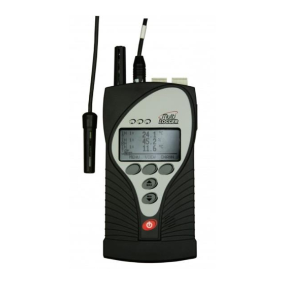
Introduction The Multilogger has been designed for measuring and recording physical and electric quantities with an adjustable logging interval from 1 second to 24 hours. The device is equipped with 4 inputs (connectors) for external probes or signals. Moreover, some versions also include an internal atmospheric pressure and/or CO concentration sensor. - Page 4 Multilogger drawing: * only certain models...
-
Page 5: General Safety Precautions
General safety precautions The following list of precautions serves to reduce risk of injury or damage of described instrument. To prevent injuries use instrument accordingly with rules in this manual. Installation and service need to be performed by qualified persons only. -
Page 6: Getting Started
(supplied accessories). For more information, see Chapter “POWER SUPPLY OF MULTILOGGER”. Install Atal Vision software to your PC. If you purchased a license for full version, register it. Connect Multilogger with your PC - you can use the USB, Ethernet or RS232 port (special cable necessary). -
Page 7: Multilogger In Stationary Application
For more information, see Chapter “CONNECTING WITH THE COMPUTER”. Device settings - use Atal Vision software to set up the device in accordance with the connected probes and your requirements. If needed, check the alarms functionality. For more information, see Chapter “DEVICE SETUP USING SOFTWARE”. -
Page 8: Installation Instruction
Installation instruction Location of Multilogger must match the operating conditions and not allowed manipulations. Working position of the device: Multilogger placed on a horizontal, nonflammable surface ( horizontal working position is not suitable for devices with thermocouple inputs and for devices with cable-less probes). - Page 9 The way of mounting the holder to Multilogger and mounting holes dimensions: EML-AC01 EML-AC02...
- Page 10 EML-AC04...
-
Page 11: Recommendations For Mounting
Recommendations for mounting Do not mount Multilogger near sources of interference (Multilogger must not be mounted directly to power switchboard nor to its nearness. Also do not mount data logger near power contactors, motors, frequency converters and other sources of strong interference). ... - Page 12 Do not use cables longer than 30 m generally; for RTD sensors is recommended max. 15 m; cables must be installed only in interior areas. Do not interconnect the inputs with other measuring systems. Use shielded cables for the voltage and current inputs - connect the shielding to the Multilogger but not to the end devices if these do not have a special terminal for it.
- Page 13 Do not use common leads for several inputs. It is recommended to earth larger systems with Multilogger at one point - the GND terminal of the alarm output can be used for this purpose. This grounding will work correctly if the system would not be grounded currently at another point too.
-
Page 14: Inputs Of Multilloger
DC Voltage - 18 mV to +18 mV DC Voltage - 60 mV to +140 mV Universal input with terminals DC current 0 to 20 mA DC voltage 0 to 10 V binary signals EML-01 EML-02 EML-03 EML-08 EML-04 EML-05 EML-06 EML-07... -
Page 15: Input Connectors
Input connectors The Multilogger does not have galvanically isolated inputs. For this reason, only devices that are not connected to any other circuit may be connected to the inputs of Multilogger. Simplified circuit diagram of inputs is shown in Appendix 3. MiniDIN connector _______________________________ It is used for connecting the TRHD-102…, TRHD-103…, Pt1000... - Page 16 Two voltage ranges are available on each universal thermocouple connector for measuring small voltages: range -60 mV to +140 mV range -18 mV to +18 mV white uncompensated connector connected according to the picture. Terminals ______________________________________ Inputs (0 to 20) mA, (0 to 10) V, binary inputs and the counter are equipped with a two-part, self-locking WAGO terminal block.
- Page 17 Connection of the transmitter with voltage output: Connection of the transmitter with the current output (active): Connection of the transmitter with the current output (passive):...
-
Page 18: Alarm Output
Alarm output This output is accessible on terminals on the bottom side of the Multilogger. Here are available these signals: OUT - open collector transistor, +5V power supply from external power source and GND terminal (see also the diagram in Appendix 2). As the default, this output transistor is switched during selected alarms. -
Page 20: Power Supply Of Multilogger
Power supply of Multilogger The Multilogger is powered from three AA batteries and optionally also from an external +5 V DC power supply, which can be also used for charging the batteries. A simplified schematics of the internal supply circuits is showed in Appendix 2. - Page 21 b) the charging process will start if the NiMH charging accumulators are selected in the device configuration c) when the Multilogger is turned off, the batteries cannot be charged d) the Multilogger allows for two battery charging modes - high current fast charging mode and low current slow charging mode ...
- Page 22 Battery replacement: a) Switch the Multilogger off. b) Remove the battery cover, take out the old batteries and insert new batteries (take care for correct polarity). Battery polarity is shown on its holder. c) Switch the Multilogger on and make sure the set time is correct (device menu View settings - General settings).
-
Page 23: Keyboard Operation
Keyboard operation Control and indication parts The front panel of the Multilogger includes 6 keys, 3 indication LED diodes and a graphic display. The red key with the switch symbol is used for Multilogger turning on/ off. The MIN/MAX keys (with the arrows) are used for quick show of the minimal and maximal measured values and also for moving through menu items. -
Page 24: Basic Display Operation
Basic display operation Current measured values (or min/max) and their units are shown on the device display. To make it easier, the short description of measured quantity, the corresponding input number or a user description of the input, can be optionally displayed. Using the VIEW multifunction key, you can switch among these views on the display. - Page 25 active recording of analog values (in the “during alarm only” or “controlled by an external input” recording modes) inactive recording of analog values (in the “during alarm only” or “controlled by an external input” recording modes) external power supply present (if the status line is occupied by icons of a higher priority, it is not displayed) minimal measured values are displays maximum measured values are displays...
-
Page 26: Main Menu
Main menu Some device settings can be viewed or modified directly on the device using the keyboard. Main menu items: 1. System Information 2. Viewing settings 3. Change the Display 4. Device Settings 5. Clear Min/Max 6. Clear Latched alarm 7. - Page 27 c) Real time clock circuit state: tick - OK, exclamation mark - low voltage of the real time clock circuit detected, the time could be incorrect! d) Activities of the Alarm out signal: tick - active, field without a tick - inactive. e) MUTE activated: tick - was activated (alarm is still active), field without a tick - was not activated (or the alarm is inactive).
- Page 28 3. Display settings _______________________________ Allows to set the parameters of the displaying: Font size (large, medium, small) Displaying input description of the measured quantity (yes, no) Order of the displayed channels (based on the input number, based on the channel number, selection) 4.
- Page 29 6. Deactivation of Latched alarm ____________________ If the “Latched alarms” function is enabled in the device configuration, the active alarms are not reset when the measured values return back to the allowed limits. Instead, they remain active until they are deactivated by the user.
-
Page 30: Connecting With The Computer
Atal Vision software. c) Connect the Multilogger into your LAN (Ethernet cable is not included as device accessory). d) Launch the Atal Vision software and add the Multilogger to the list of your devices. The Multilogger automatically identifies which communication interface is connected and will use it for communication. -
Page 31: Software Atal Vision
2, Net framework version 4 Program description ______________________________ The Atal Vision software can be used for device configuration and for obtaining recorded data and currently measured values. The device can be connected via USB, Ethernet or a serial port. - Page 32 How to work with the program ______________________ The main menu of the program is on the right side with items: “Home”, “Devices”, “Files” and “Displays”. These components control appearing bookmarks. Each item has its bookmarks, one of them named “Home” is similar for all items. The other options are specific for each item.
-
Page 33: Device Setup Using Software
Complete configuration of the device can be done using the Atal Vision software. Some parameters can be changed from the device keyboard or from its web pages. When editing the Multilogger... - Page 34 General - Preferences ____________________________ Here you can select language localization Language on the device terminal, Default temperature unit °C/°F and, for some models, Atmospheric pressure unit. If your model does not measure atmospheric pressure but it is necessary to know it (for calculated humidity values and CO concentration), you need to specify Ambient average pressure.
- Page 35 General - Advanced - Device start ___________________ Here you can disable the “Off key” of the device. General - Advanced - LCD Display __________________ These settings are used for optimizing the backlight of the display in relation to your application. As a default, the Multilogger is set in a way that the backlight (LCD backlight activity) is activated only for several seconds upon the last key pressing.
- Page 36 Recording can be continuous or, alternatively, records can be taken only if any measured quantity is in the alarm state (the system alarms does not trigger recording). Moreover, Multilogger with binary input No. 3 also offer the option to control the recording by the status of this binary input.
- Page 37 It can be optionally applied to acoustic signalization, the ALARM OUT output or both. It can be performed from the keyboard, from the web or from the software Atal Vision. To protect access to these functions, you can use the PIN2 code, which the operation personnel must enter.
- Page 38 Alarm events - Memory occupation __________________ If you need to indicate exceeding of your specified limit of the data memory occupation, use the setup in this section. The signalization can be selected as optical (red LED diode), acoustic, or by the means of the ALARM OUT output activation or sending email to selected recipients.
- Page 39 Ethernet - General _______________________________ Here, you can make the basic connection setup of the Ethernet interface. To obtain some information, you will need to contact your computer network administrator. First of all, you have to find out if you are going to use a fixed IP address or if it will be assigned by the DHCP server in your network.
- Page 40 You can use shortened emails (Short email) especially for forwarding them as SMS messages to mobile phones. You can also insert your own comments to the emails: if the alarm appears (Alarm note), if the alarm expires (Clear alarm note), in the case of system alarm (System alarm note) and in the case of exceeding the memory occupation limit (Memory overflow note).
- Page 41 Inputs _________________________________________ Here you can specify the quantities that you will measure on every one inputs, their recording and alarm states. You can see a simple list of all inputs and measured quantities on the screen. First of all, specify the probe or signal types connected to each input (Settings button).
- Page 42 Next, select if the alarm occurs upon exceeding or dropping under the given limit value (value is greater than / value is lower than) and enter this limit. For binary inputs only define the state of the input. Next, you need to specify the alarm delay (for the duration of), which is used for eliminating short-term exceeding of the limit value.
-
Page 43: Applications Notes
Applications notes Recommended settings for the portable application______ In this application, the Multilogger is powered from batteries and a fast response time and an easy battery recharge after the measurement are required. Recorded data are downloaded after measurement. We recommend to use the Multilogger with NiMH accumulators; specify the following device configuration: ... - Page 44 Set the acoustic alarm signalization as needed. If you want to operate the Multilogger “remotely”, disable “Off key” on its keyboard (Atal Vision software, option General - Advanced - Device start). You will thus prevent unauthorized or unwanted device turn-off by unqualified personnel.
- Page 45 Recommended settings for a long time battery powered application ______________________________________ In this application, the Multilogger is powered only from batteries and a fast response to changing measured quantities is not required, however, it is required that the device runs from the batteries as long as possible.
- Page 46 If the Multilogger is not equipped with an internal pressure sensor, you have to enter this value using the SW in the device configuration, item General - Preferences. You can enter either the current pressure value at the given location (without conversion to the sea level) or the current altitude.
- Page 47 Multilogger reports this error, the batteries are empty. You can check the battery status in the System information menu or in the software Atal Vision on the Device home page. If the battery voltage drops under 3.45 V, the Multilogger reports a self-test error. A drop of the power supply voltage is also indicated by the given symbol the device status line.
- Page 48 A similarly for sensors with a voltage or current output - unwanted couplings can cause incorrect measurements. If the Multilogger reports an error state, you can find more information in Appendix 1 - Selected error messages. Another group of problems are random spikes of the measured values.
-
Page 49: Operation And Maintenance Recommendations
Operation and maintenance recommendations Device operation in various applications _______________ Before application it is necessary to consider if Multilogger is suitable for required purpose, adjust optimal configuration and create instructions for its periodical metrological and functional inspections. Since the Multilogger can be powered from the power mains, it is necessary (depending on the character of the application) to secure the appropriate electric revision of its installation and its regular inspections. - Page 50 Recommendations for metrological verification _________ Metrological verification is performed in accordance with application requirements specified by the user. In some cases, calibrations must be performed by the accredited laboratory. The manufacturer recommends to perform these verifications once a year. Note: accuracy of Multilogger input means accuracy of input itself without probes.
- Page 51 Verification of cabling - check the connection quality of cables, check visually entire cable length for damage and the route of cables for interference, especially whether some parallel power wires are not near. Visual inspection of sensors - perform their visual inspection and make sure no water has leaked inside the sensors;...
-
Page 52: Technical Parameters
Technical parameters Power supply The Multilogger is powered from batteries located under the removable cover on the rear side of the device. An external power supply source can be also connected to the Multilogger. When the device is connected to an external power supply, the batteries are not used. - Page 53 Backing up of date and time in the Multilogger: < 5 minutes after removing the batteries and with the device turned off ________________________________________________________________________________________________ If the Multilogger is without a power for a longer time, the date and time settings in the device could be lost and will have to be set up again.
-
Page 54: Alarm Out Output
Fast charging mode current: approximately 350 mA ________________________________________________________________________________________________ Fast charging has to be activated by the Multilogger user. During the fast charging, the Multilogger does not take any measurements nor recording and does not communicate with the computer. Fast charging time: Up to 6 hours Fast charging restriction: Allowed in ambient temperature from 0 °C to 40 °C. -
Page 55: Communication Interfaces
Communication interfaces The Multilogger is equipped with USB, Ethernet and RS232C interfaces with automatic detection of a connected cable. Only one of these interfaces can be used for communication at one time. The USB interface has the highest priority (if the Multilogger is connected via its USB port, the other two interfaces are automatically disabled) while the Ethernet interface has the lowest priority (for its proper function, it is necessary that neither the RS232C nor the USB interfaces are connected). -
Page 56: Measuring, Data Memory And Real Time Clock
Ethernet _______________________________________ Compatibility: 10/100 MBit Ethernet, galvanically isolated Connector for Ethernet: RJ45 Measuring, data memory and real time clock Measuring interval (except CO 1 s in standard mode (default) 10 s in the energy saving mode measuring interval: 2 minutes in standard mode 10 minutes in the energy saving mode Recording interval: 1 s, 2 s, 5 s, 10 s, 15 s, 30 s,... -
Page 57: Operation And Storage Conditions
Immunity: EN 61000-4-2: class A (4/8 kV) EN 61000-4-3: class A (3V/m) EN 61000-4-4: class A (0.5/1 kV) EN 61000-4-5: class A (external power supply only) EN 61000-4-6: class A (3 V) Operation and storage conditions Operation temperature: (-10 to +60) °C Operation humidity: (5 to 85) %RH without condensation Storage temperature:... -
Page 58: Technical Parameters Of The Inputs
Connectivity, input ranges and accuracy are determined by connector types which are specific for each model. Required measured quantities can be selected for each input using the Atal Vision software. These quantities can be recalculated using two-point linear transformation, displayed, recorded to the memory or used for alarming. - Page 59 Digi /M digital probe for measuring temperature and humidity. Measured quantities: Temperature Relative humidity Calculated quantities: Dew point _______________________________________________________________________ For negative temperatures, the Multilogger calculates a dew point, no frost point. Absolute humidity Specific humidity Mixing ratio Specific enthalpy Measurement range and accuracy: According to the connected probe.
- Page 60 In order to secure correct measurements, you need to prevent undesirable coupling. Furthermore, the Multilogger has to be placed in its working position and temperature stabilized. Models equipped with this input: EML-02 Input 1 Input 2 Input 3 Input 4...
- Page 61 Cold junction: compensated in the temperature range of (-10 to 60) °C ______________________________________________________________________________________ *) to achieve this value, the corresponding number of decimal places must be set Thermocouple of the “S” type (Pt10%Rh-Pt) Measured quantity: temperature Range: (0 to 1,700) °C Accuracy (without probes) ±...
- Page 62 Accuracy (without probes) ± (0.3% from the measured value of + 1.5 °C) Resolution: better than 0.1 °C *) Cold junction: compensated in the temperature range of (-10 to 60) °C ______________________________________________________________________________________ *) to achieve this value, the corresponding number of decimal places must be set ...
- Page 63 Connector: miniature uncompensated thermocouple connector (white color) DC voltage from -18 mV to +18 mV Range: (-18 to +18) mV Accuracy: ± 20 uV Resolution: better than 0.5 uV *) Input impedance Ω approximately 10 Minimum allowable input voltage: -0.2 V Maximum allowable input voltage: +3 V...
- Page 64 Universal input with a terminal ______________________ The input is equipped with two-part removable terminal block with four wires. The inputs are not galvanically isolated from each other, nor from other signals connected to the Multilogger. In order to secure correct measurements, you need to prevent undesirable coupling.
- Page 65 Range: (0 to 20) mA DC Accuracy: ± 20 uA Resolution: better than 0.1 uV *) Input impedance approximately 100 Ω Minimum allowable input current: 0 mA (disconnected circuit) Maximum allowable input current: limited to approximately 40 mA Maximum cable length: maximum of 30 meters ______________________________________________________________________________________ *) to achieve this value, the corresponding number of...
- Page 66 approximately 3 V _________________________________________________________________________________ In order to work properly, the device equipped with a “transistor with an open connector” can require a higher voltage than Multilogger is able to supply. Moreover, you should also make sure that the voltage in the “switched on”...
- Page 67 Internal barometric sensor_________________________ Models equipped with this sensor: EML- barometric pressure EML- barometric pressure Parameters: Measured quantity: barometric pressure (absolute) Range: 600 hPa to 1,100 hPa Accuracy: ±1.3 hPa at 23 °C Other options: recalculation to the sea level Supported physical quantities: hPa, kPa, mbar, mmHg, inHg, inH O, PSI, oz/in Internal CO...
-
Page 68: Appendixes
Appendixes Appendix 1: Selected error messages Error Description and solution The value is out of the input range (low limitation). - shorted Pt1000 probe - negative input voltage (thermocouples, 0 to 10 V) Error 1 - reverse input current (for 0 mA to 20 mA range) Check the connected probes and signals! The value is out of the input range (high limitation). - Page 69 Error Description and solution The CO concentration sensor is not available or does not Error 12 work correctly. Error 16 Send the Multilogger for repair. The source value for the calculated channel is not available. Error 19 Check calculated channel settings and its source values. Error 20 Calculation error, incorrectly calibrated device.
-
Page 70: Appendix 2: Output And Power Supply Circuits
Appendix 2: Output and power supply circuits... -
Page 71: Appendix 3: Input Circuits
Appendix 3: Input circuits... -
Page 72: Appendix 4: Connecting Of Pt1000 Rtd Probe
Appendix 4: Connecting of Pt1000 RTD probe It is recommended to use the intelligent probes Pt1000 with the Multilogger. May be that the connection of the standardize RTD Pt1000 probe will be necessary. In this case you can connect this probe in accordance with drawing shown below.
Need help?
Do you have a question about the EML-02 and is the answer not in the manual?
Questions and answers