Moxa Technologies NPort 6450 Series Quick Installation Manual
Hide thumbs
Also See for NPort 6450 Series:
- Quick installation manual (7 pages) ,
- User manual (208 pages) ,
- Brochure & specs (31 pages)
Table of Contents
Advertisement
Quick Links
NPort 6450 Series
Quick Installation Guide
Fifth Edition, May 2013
Overview
The NPort 6450 secure serial device servers provide reliable
serial-to-Ethernet connectivity for a wide range of serial devices.
The NPort 6450 supports TCP Server, TCP Client, UDP, and
Pair-Connection operation modes to ensure the compatibility of
network software. In addition, the NPort 6450 also supports
Secure TCP Server, Secure TCP Client, Secure Pair-Connection,
and Secure Real COM modes for security critical applications such
as banking, telecom, access control, and remote site
management.
Package Checklist
Before installing the NPort 6450, please verify that the package
contains the following items:
•
1 NPort 6450
•
Power adaptor
•
2 wallmount ears
•
Quick installation guide
•
Documentation and software CD
•
Warranty card
Optional Accessories
•
DK-35A: 35 mm DIN-rail mounting kit
•
DIN-rail power supply
•
CBL-RJ45M9-150: 8-pin RJ45 to male DB9 cable
•
CBL-RJ45M25-150: 8-pin RJ45 to male DB25 cable
•
NM-TX01: Network module with one 10/100BaseTX Ethernet
port (RJ45 connector; supports cascade redundancy and
RSTP/STP)
•
NM-FX01-S-SC: Network module with one 100BaseFX single
mode fiber port (SC connector; supports cascade redundancy
and RSTP/STP)
•
NM-FX02-S-SC: Network module with two 100BaseFX single
mode fiber ports (SC connectors; supports cascade
redundancy and RSTP/STP)
•
NM-FX01-M-SC: Network module with one 100BaseFX multi
mode fiber port (SC connector; supports cascade redundancy
and RSTP/STP)
•
NM-FX02-M-SC: Network module with two 100BaseFX multi
mode fiber ports (SC connectors; supports cascade
redundancy and RSTP/STP)
•
NM-Modem: One PSTN modem port with RJ11 connector
P/N: 1802066500013
– 1 –
Q-Pulse Id VM355
Lobley St SPS SP331 General (Electrical Manual (MPA) Moxa Terminal Server Nport 6450 Quick Installation Guide) General
NOTE Please notify your sales representative if any of the above
items are missing or damaged.
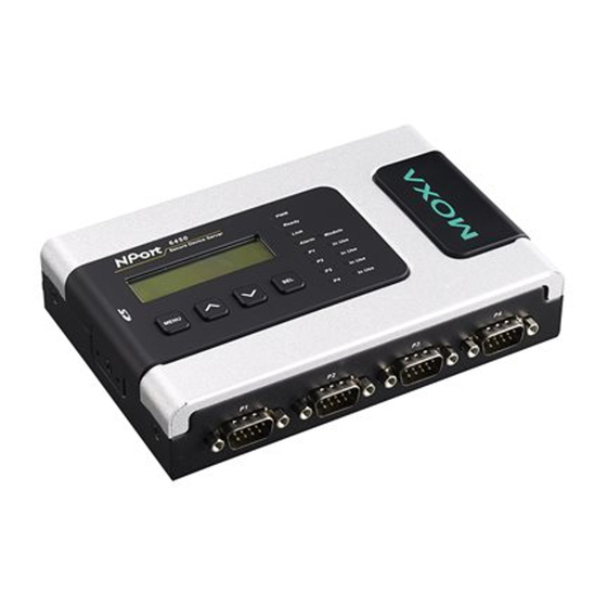
Hardware Introduction
Reset Button—Press the Reset button continuously for 5 sec to
load factory defaults. Use a pointed object, such as a straightened
paper clip or toothpick, to press the reset button. This will cause
the Ready LED to blink on and off. The factory defaults will be
loaded once the Ready LED stops blinking (after about 5 seconds).
At this point, you should release the reset button.
– 2 –
Active 26/09/2013
LED Indicators
Name
Color
Function
PWR
Red
Power is being supplied to the power input.
Ready
Red
Steady on: NPort is booting up.
Blinking:
IP conflict, DHCP or BOOTP
server problem, or relay output
problem.
Green
Steady on: Power is on and the NPort 6450
is functioning normally.
Blinking:
NPort is responding to Locate
function.
Off
Power is off, or power error condition exists.
Link
Orange
10 Mbps Ethernet connection.
Green
100 Mbps Ethernet connection.
Off
Ethernet cable is disconnected, or has a
short.
P1-P4
Orange
Serial port is receiving data.
Green
Serial port is transmitting data.
Off
Serial port is idle.
FX
Orange
Steady on: Ethernet port is idle.
Blinking:
Fiber port is transmitting or
receiving data.
Alarm
Red
The relay output (DOUT) is open
(exception).
Off
The relay output (DOUT) is shorted (normal
condition).
Module
Green
A network module has been detected.
Off
No network module is present.
Adjustable pull high/low resistor for RS-422/485
(150 KΩ or 1 KΩ)
Jumpers are used to set
the pull high/low resistors.
The default is 150 KΩ.
Short the jumpers to set
this value to 1 KΩ. Do not
use the KΩ setting with
RS-232 mode, since doing
so will degrade the RS-232
signals and shorten the
communication distance.
– 3 –
Page 1 of 2
Advertisement
Table of Contents

Related Manuals for Moxa Technologies NPort 6450 Series


Summary of Contents for Moxa Technologies NPort 6450 Series
- Page 1 NOTE Please notify your sales representative if any of the above items are missing or damaged. Name Color Function NPort 6450 Series Hardware Introduction Power is being supplied to the power input. Quick Installation Guide Ready Steady on: NPort is booting up.
- Page 2 Lobley St SPS SP331 General (Electrical Manual (MPA) Moxa Terminal Server Nport 6450 Quick Installation Guide) General Environmental Limits Hardware Installation Procedure Specifications Operating 0 to 55°C (32 to 131°F), 5 to 95% RH STEP 1: Connect the 12-48 VDC power adaptor to the NPort 6450 Temperature and then plug the power adaptor into a DC outlet.
Need help?
Do you have a question about the NPort 6450 Series and is the answer not in the manual?
Questions and answers