Table of Contents
Advertisement
Quick Links
Advertisement
Table of Contents

Related Manuals for Sper scientific 850011


Summary of Contents for Sper scientific 850011
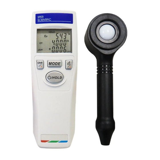
- Page 1 Chroma Light Meter 850011 Instruction Manual...
- Page 2 Chroma Light Meter - 850011 Copyright ©2021 by Sper Scientific ALL RIGHTS RESERVED The contents of this manual may not be reproduced or transmitted in any form or by any means electronic, mechanical, or other means that do not yet exist or may...
-
Page 3: Table Of Contents
TABLE OF CONTENTS PRODUCT INTRODUCTION ....4 SAFETY INFORMATION ......5 LCD AND CONTROL PANEL . -
Page 4: Product Introduction
PRODUCT INTRODUCTION • Illuminance in Lux or FC • Color temperature and correlated color temperature • Custom reference value of color difference Enables precise measurement of illuminance, color temperature, correlated color temperature or color differ- ence simultaneously shown on a backlit display. Excellent for art galleries and museums, film and TV studios, lighting manufacturers, stores and designers. -
Page 5: Safety Information
SAFETY INFORMATION Read the following safety information carefully before at- tempting to operate or service the meter. Only qualified personnel should perform repairs. Safety Symbols CE Certification. This instrument conforms to the following standards: EN61326: Electrical equipment for measurement, control and laboratory use. - Page 6 Precautions Be sure to adhere to the following points to avoid injury. • Please read the manual carefully to ensure safe and correct use of this meter before using. Please reread if necessary. • Do not immerse the meter in water. •...
-
Page 7: Lcd And Control Panel
LCD AND CONTROL PANEL A. Data Hold Symbol J. Secondary Reading B. SET Function Symbol K. Light Source Symbol C. Low Battery Symbol (FL, INC or LED) (522) D. Measuring Symbols of L. Tertiary Reading Primary Reading M. Unit / Down Button E. -
Page 8: Rear
REAR Q. Tripod Socket R. Battery Cover S. Magnet Position T. Anti-slippery Pad PROBE U. Receptor Head V. Receptor Cover W. Grip... -
Page 9: Measurement Procedure
OPERATION INSTRUCTION Main Function Power On/Off Press and hold the Power button for 2 seconds to turn the meter on and all of symbols will appear for 2 seconds on the LCD. After power-on, the meter will measure and show the readings on the LCD continuously. - Page 10 Data Hold While measuring, press the HOLD button once to freeze the display. HOLD will appear on the LCD. Press HOLD button again to resume measuring.
- Page 11 Measuring Modes Press MODE and buttons simultaneously to switch between color measurement and color difference. Each has 3 modes: • Color Measurement: 1. Ev, x, y (Illuminance, Color coordinate) 2. Ev, u’, v’ (Illuminance, Color coordinate, CIE1960) 3. Ev, CT, uv (Illuminance, Color temperature) Press the MODE button to select your color management mode.
- Page 12 Measuring Modes Diagram...
- Page 13 LCD Display in Color Measurement Mode 1. Ev, x, y (Illuminance, Color Coordinate) 2. Ev, u (Illuminance, Color Coordinate, CIE1960) ’ ’ 3. Ev, CT, uv (Illuminance, Color Temperature)
- Page 14 LCD Display in Color Diffference Mode 1. Ev, x, y (Color Difference of Illuminance and Color Coordinate) 2. Ev, u (Color Difference of Illuminance and Color ’ ’ Coordinate, CIE1960) 3. Ev, CT(522), ((Color Difference of Illuminance ’ ’ and Color Temperature)
- Page 15 SET Function Color Difference: This function allows you to set certain reference values (Ev , u’ , v’ , CT (522)) to compare with the target color. Set the Reference Value You can select one of these color difference modes to set: u’, v’...
- Page 16 Set the reference values in either of two methods: 5-2-1. Use the measured values and adjust it manually as the reference values. 5-2-2. Use previous values stored in memory and adjust manually as the reference values. The difference between method 5-2-1 and 5-2-2 is whether the Data Hold was enabled before entering the set mode.
- Page 17 Using the Measured Values Select the (Ev, x, y) mode first and measure a light source. 1. Press the HOLD button to hold these values that you want to use as your reference values. 2. Press the button once to toggle the color difference mode.
- Page 18 c. Select the (Ev, CT, uv) mode and repeat step 1~7 to set the CT reference values. (522) → → CT → → Color difference mode Please note that the Ev reference value in the three modes (Ev, x, y ,Ev, u’, v’ and Ev, CT, uv) remains the same.
- Page 19 a. Using the measured values to set the reference values of ( Ev, y) mode.
- Page 20 b. Using the measured values to set the reference values of ( u’, v’) mode.
- Page 21 c. Using the measured values to set the reference values of ( u’v’) mode.(522)
- Page 22 Using the previous values stored in memory a. Select the color different ( Ev, x, y) mode directly. 1. Press the button and hold for 3 seconds to toggle reference values mode wihout Data Hold. 2. The SET symbol will appear and the Ev symbol will flash on the LCD.
- Page 23 a. Using the previous values to set the reference values of ( Ev, y) mode.
- Page 24 b. Using the previous values to set the reference values of ( u’, v’) mode.
- Page 25 c. Using the previous values to set the reference values of ( u’v’) mode.(522) Zero the Reference Values of Color Difference Close the sensor cover and the (Ev, x, y ,Ev, u’, v’ or EV, CT) measured values will show zero. Then repeat the section 5-2-1: using the measured values to zero the reference value.
-
Page 26: Maintenance
MAINTENANCE Clean the Receptor Head: Blow off loose particles using clean compressed air. Gently brush remaining debris sway with a camel’s hair brush. Carefully wipe the surface with a cotton swab. The swab may be moistened with some water. Clean the Housing: When you clean the meter, wipe it with soap and water on a damp sponge or soft cloth. -
Page 27: Battery Replacement
BATTERY REPLACEMENT The meter is powered by a 9V battery. When appears, battery voltage has dropped below the level for reliable operation, and the battery should be replaced. Turn the meter off, open the battery cover on the back and replace the battery. -
Page 28: Specifications
SPECIFICATIONS... - Page 29 NOTES:...
-
Page 30: Warranty
WARRANTY Sper Scientific warrants this product against defects in materials and workmanship for a period of five (5) years from the date of purchase, and agrees to repair or replace any defective unit without charge. If your model has since been discontinued, an equivalent Sper Scientific product will be substituted if available.
Need help?
Do you have a question about the 850011 and is the answer not in the manual?
Questions and answers