Hitachi YUTAKI ATW-YCC-03 Installation And Operation Manual
Cascade controller
Hide thumbs
Also See for YUTAKI ATW-YCC-03:
- Installation & operation manual (176 pages) ,
- Installation & operation manual (364 pages) ,
- Installation and operation manual (294 pages)

Related Manuals for Hitachi YUTAKI ATW-YCC-03


Summary of Contents for Hitachi YUTAKI ATW-YCC-03
- Page 1 – INSTALLATION AND OPERATION MANUAL – YUTAKI CASCADE CONTROLLER MODELS ATW-YCC-03 PMEN0581 rev.2 - 04/2023...
- Page 2 The English version is the original one; other languages are translated from English. Should any discrepancy occur between the English and the translated versions, the English version shall prevail. La versión en inglés es la original, y las versiones en otros idiomas son traducciones de la inglesa. En caso de discrepancias entre la versión inglesa y las versiones traducidas, prevalecerá...
- Page 3 English Original version Español Versión traducida Deutsch Übersetzte Version Français Version traduite Italiano Versione tradotta Português Versão traduzidal Dansk Oversat version Nederlands Vertaalde versie Svenska Översatt version Ελληνικα Μεταφρασμένη έκδοση Български Преведена версия Čeština Přeložená verze Magyar Lefordított változat Lietuvių Versta versija Polski Tłumaczenie wersji oryginalnej...
- Page 4 Contents General information .....................1 General Data ......................7 Installation ......................11 LCD remote controller ..................15 Electrical and control settings ................36 PMEN0581 rev.2 - 04/2023...
-
Page 5: Table Of Contents
General Index 1. General information ....................1 1.1 General information ..................2 1.2 Safety .........................2 1.2.1 Applied symbols ..................2 1.2.2 Additional information about safety ............3 1.3 Important notice ....................4 1.4 Factory-supplied unit components ..............4 1.5 Introduction .......................5 2. General Data .......................7 2.1 General Data ......................8 2.2 General dimensions ...................8 2.2.1 Service space ...................8 2.2.2 Name of parts ..................9 2.2.3 Dimensional data ...................10... - Page 6 4.4.1 Individual Heating/Cooling household in combination with common DHW production ..................24 4.4.2 Individual Heating/Cooling household in combination with Individual DHW production ..................26 4.4.3 Individual Heating/Cooling household in combination with Individual DHW production (II) ................28 4.4.4 Common Heating/Cooling household in combination with common DHW production ..................30 4.4.5 Common Heating/Cooling household in combination with Individual DHW production ..................32 4.4.6 Common Heating/Cooling household in combination with Individual...
-
Page 7: General Information
General information 1.1 General information ..................2 1.2 Safety .........................2 1.2.1 Applied symbols ..................2 1.2.2 Additional information about safety ............3 1.3 Important notice ....................4 1.4 Factory-supplied unit components ..............4 1.5 Introduction .......................5 PMEN0581 rev.2 - 04/2023... -
Page 8: General Information
This document may therefore have been subject to amendments during the life of the product. Hitachi makes every effort to offer correct, up-to-date documentation. Despite this, printing errors cannot be controlled by Hitachi and are not its responsibility. -
Page 9: Additional Information About Safety
proximities of the unit. • Not taking these instructions into account could lead to unit damage. In the text following the caution symbol you can also find information on safe procedures during unit installation. NOTE • The text following this symbol contains information or instructions that may be of use or that require a more thorough explanation. -
Page 10: Important Notice
If this is not the case, contact your distributor. • Hitachi pursues a policy of continuous improvement in product design and performance. The right is therefore reserved to vary specifications without notice. -
Page 11: Introduction
1.5 Introduction The YUTAKI CASCADE CONTROLLER is designed as an extension of the hydraulic control of YUTAKI range to establish a larger and efficient heating or cooling system. When YUTAKI CASCADE CONTROLLER function is active, system separate water generation (hot or cold) from water distribution and consumption. - Page 12 RECEIVER ATW-YCC-03 ATW- RTU-07/08 YUTAKI H-LINK YUTAKI YUTAKI YUTAKI HYDRAULIC SEPARATOR CIRCUIT 2 YUTAKI SPACE HEATING/COOLING PC-ARFH2E YUTAKI ATW- RTU-07/08 UP to 8 UP to 8 Example for illustrative purpose PMEN0581 rev.2 - 04/2023...
-
Page 13: General Data
General Data 2.1 General Data ......................8 2.2 General dimensions ...................8 2.2.1 Service space ...................8 2.2.2 Name of parts ..................9 2.2.3 Dimensional data ...................10 PMEN0581 rev.2 - 04/2023... -
Page 14: General Data
2.1 General Data Item Units Description Power supply ~ 230V 50Hz Max Input Dimensions (HxWxD) 490 x 360 x 100 Weight (Gross/Net) 6.15/5.45 Mounting conditions Indoor 2.2 General dimensions 2.2.1 Service space Place the YUTAKI CASCADE CONTROLLER to an accessible place, accordingly to main users. Please keep in mind that the unit should be easily disassembled for maintenance or servicing. -
Page 15: Name Of Parts
2.2.2 Name of parts Electrical Box Terminal Board (TB1) Terminal Board (TB2) Relay (AR1) Fuse (EF1) and Fuse holder Switch for DHW emergency operation Earth screw Model Label (Bottom) Electrical data label (Bottom) Service cover LCD unit controller assembly holes (x2) LCD unit controller routing hole Wall mounting holes (x4) Service cover assembly hooks (x2) -
Page 16: Dimensional Data
2.2.3 Dimensional data (mm) ◆ YUTAKI CASCADE CONTROLLER with PC-ARFH2E Electrical data label Model label PMEN0581 rev.2 - 04/2023... -
Page 17: Installation
Installation 3.1 Installation .......................12 3.2 Fix the unit to the wall ..................13 3.2.1 Dimensional for the installation to a wall ..........13 3.2.2 Notes for installation ................14 PMEN0581 rev.2 - 04/2023... -
Page 18: Installation
3.1 Installation CAUTION • Transport the products as close as possible to the place to be installed before unpacking. • Do not put any material on the product. DANGER • Install the device with enough clearance and space around it for operation and maintenance. Install the YUTAKI CASCADE CONTROLLER where good ventilation is available •... -
Page 19: Fix The Unit To The Wall
3.2 Fix the unit to the wall The YUTAKI CASCADE CONTROLLER is a simple-to-install device. To make this operation even simpler, the YUTAKI CASCADE CONTROLLER disposes of 4 key slots to ease the operation of fixing to a wall. CAUTION Place the unit on a resistant wall 3.2.1 Dimensional for the installation to a wall Ø6... -
Page 20: Notes For Installation
3.2.2 Notes for installation The YUTAKI CASCADE CONTROLLER is designed in a way that wiring must be route through the bottom side of the unit. Rubber bushing have been placed for such purpose. After routing the cables through the rubber bushing, the cables should be placed in a simple manner inside the Electrical box, so the identification should be easy and at first sight. -
Page 21: Lcd Remote Controller
LCD remote controller 4.1 Definition of the switches ................16 4.2 Description of the icons ..................17 4.3 Cascade controller configuration ..............20 4.4 Configuration examples ...................24 4.4.1 Individual Heating/Cooling household in combination with common DHW production ..................24 4.4.2 Individual Heating/Cooling household in combination with Individual DHW production ..................26 4.4.3 Individual Heating/Cooling household in combination with Individual DHW production (II) ................28 4.4.4 Common Heating/Cooling household in combination with common DHW production ..................30 4.4.5 Common Heating/Cooling household in combination with Individual DHW production ..................32 4.4.6 Common Heating/Cooling household in combination with Individual DHW production (II) ................34 PMEN0581 rev.2 - 04/2023... -
Page 22: Definition Of The Switches
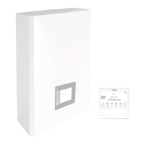
The new YUTAKI CASCADE CONTROLLER for YUTAKI series (PC-ARFH2E) is an user-friendly remote control which ensures a strong and safe communication through H-LINK. 4.1 Definition of the switches Liquid Crystal Display Screen where controller software is displayed. OK button To select the variables to be edited and to confirm the selected values. -
Page 23: Description Of The Icons
4.2 Description of the icons Icon Name Explanation Circuit I or II is in Demand-OFF Circuit I or II is on Thermo-OFF Status for circuit Circuit I or II is working between 0 < X ≤ 33% of the desired water outlet 1, 2, DHW and temperature swimming pool. - Page 24 Icon Name Explanation This icon informs about pump operation. Pump There are three available pumps on the system. Each one is numbered, and its corresponding number is displayed below to the pump icon when it is operating Heater step Indicates which of the 3 possible heater steps is applied on space heating DHW Heater Informs about DHW Heater operation.
- Page 25 Icon Name Explanation Night Shift Informs about night shift operation Informs about the activation of the “CASCADE” mode. CASCADE CONTROLLER CASCADE CONTROLLER in alarm state Fan stopped by Informs about the stopagge of fan 1 or 2 by Demand OFF Demand OFF PMEN0581 rev.2 - 04/2023...
-
Page 26: Cascade Controller Configuration
4.3 Cascade controller configuration • Select the desired language using the arrow keys. • Press OK button. • Select the date and time using the arrow keys. • Select Enabled or Deactivated for European summer time. • Press OK button. ... - Page 27 ✓ Auto: changes automatically to light at 08:00 am and turns to dark at 20:00 pm. • Configure circuit 1 and circuit 2 OTC: Deactivated, Points, Gradient, Fix. • Enable or disable DHW and Swimming Pool. • Select the heating source: HP only, HP + EH, HP + Boiler. •...
- Page 28 • Enable or disable the desired modules (module 1 is enabled by default) • Select Next and press OK button. • Enable or disable the individual DHW for each module. • Select Next and press OK button. •...
- Page 29 • Select Yes to complete the configuration. • Press OK button to go to the main screen. PMEN0581 rev.2 - 04/2023...
-
Page 30: Configuration Examples
4.4 Configuration examples The following examples and illustrations are for illustrative purpose and do not cover all the possible installations. 4.4.1 Individual Heating/Cooling household in combination with common DHW production This installation is suitable in case a high amount of DHW at a specific setting temperature is required. - Page 31 ◆ Mainly configuration Configuration in YUTAKI CASCADE CONTROLLER Side: 1 Circuit 1: Enabled at Fixed setting temperature (Buffer tank setting temperature) 2 Circuit 2: Disabled 3 DHW: Enabled 4 Cascade Configuration Menu (Example in case that 6 modules are connected): Example 1 Module 1 Module 2...
-
Page 32: Individual Heating/Cooling Household In Combination With Individual
4.4.2 Individual Heating/Cooling household in combination with Individual DHW production This installation is suitable when there are different demands of DHW applications: ✓ Different DHW setting temperature ✓ Different DHW usage patterns ✓ Variety of DHW volume required. DHW production or Space Heating/Cooling production is simultaneously. This means that YUTAKI CASCADE CONTROLLER can operate for Space Heating/Cooling application and each configured YUTAKI Sub can operate for DHW when needed. - Page 33 ◆ Mainly configuration Configuration in YUTAKI CASCADE CONTROLLER Side: 1 Circuit 1: Enabled at Fixed setting temperature (Buffer tank setting temperature) 2 Circuit 2: Disabled 3 DHW: Disabled 4 Cascade Configuration Menu (Example in case that 6 modules are connected): Example 1 Module 1 Module 2...
-
Page 34: Individual Heating/Cooling Household In Combination With Individual
4.4.3 Individual Heating/Cooling household in combination with Individual DHW production (II) This installation is suitable in case that not such a high amount of DHW is demanded, or more than one Sub unit is needed to heat one single tank. DHW production or Space Heating/Cooling production is simultaneously. This means that YUTAKI CASCADE CONTROLLER can operate for Space Heating/Cooling application and each configured Sub can operate for DHW when needed. - Page 35 ◆ Mainly configuration Configuration in YUTAKI CASCADE CONTROLLER Side: 1 Circuit 1: Enabled at Fixed setting temperature (Buffer tank setting temperature) 2 Circuit 2: Disabled 3 DHW: Disabled 4 Cascade Configuration Menu (Example in case that 6 modules are connected): Example 1 Module 1 Module 2...
-
Page 36: Common Heating/Cooling Household In Combination With Common
4.4.4 Common Heating/Cooling household in combination with common DHW production This installation is suitable in case high amount of DHW is required at a specific setting temperature. When Cascade is generating water for DHW tank, production of hot or chilled water for Space Heating/Cooling application is stopped until DHW production stops. - Page 37 ◆ Mainly configuration Configuration in YUTAKI CASCADE CONTROLLER Side: 1 Circuit 1: Enabled at gradient/point/fixed temperature (thermostat option) (Direct Circuit) 2 Circuit 2: Enabled at gradient/point/fixed temperature (thermostat option) (Mixing Circuit) 3 DHW: Enabled 4 Cascade Configuration Menu (Example in case that 6 modules are connected): Example 1 Module 1 Module 2...
-
Page 38: Common Heating/Cooling Household In Combination With Individual Dhw Production
4.4.5 Common Heating/Cooling household in combination with Individual DHW production This installation is suitable when there are different demands of DHW applications: ✓ Different DHW setting temperature ✓ Different DHW usage patterns ✓ Variety of DHW volume required DHW production or Space Heating/Cooling production is simultaneously. This means that YUTAKI CASCADE CONTROLLER can operate for Space Heating/Cooling application and each configured Sub can operate for DHW when needed. - Page 39 ◆ Mainly configuration Configuration in YUTAKI CASCADE CONTROLLER Side: 1 Circuit 1: Enabled at gradient/point/fixed temperature (thermostat option) (Direct Circuit) 2 Circuit 2: Enabled at gradient/point/fixed temperature (thermostat option) (Mixing Circuit) 3 DHW: Disabled 4 Cascade Configuration Menu (Example in case that 6 modules are connected): Example 1 Module 1 Module 2...
-
Page 40: Common Heating/Cooling Household In Combination With Individual
4.4.6 Common Heating/Cooling household in combination with Individual DHW production (II) This installation is suitable in case that not such a high amount of DHW is demanded, or more than one Sub unit is needed to heat one single tank. DHW production or Space Heating/Cooling production is simultaneously. This means that YUTAKI CASCADE CONTROLLER can operate for Space Heating/Cooling application and each configured Sub can operate for DHW when needed. - Page 41 ◆ Mainly configuration Configuration in YUTAKI CASCADE CONTROLLER Side: 1 Circuit 1: Enabled at gradient/point/fixed temperature (thermostat option) (Direct Circuit) 2 Circuit 2: Enabled at gradient/point/fixed temperature (thermostat option) (Mixing Circuit) 3 DHW: Disabled 4 Cascade Configuration Menu (Example in case that 6 modules are connected): Example 1 Module 1 Module 2...
- Page 42 Electrical and control settings 5.1 Electrical wiring ....................37 5.1.1 Connections on the Terminal board 1 (TB1) .........37 5.1.2 Connections on the Terminal board 2 (TB2) .........37 5.1.3 Wiring size and minimum requirements of protection device .....41 5.2 Optional unit wiring (accessories) ..............42 5.3 Location of DIP switches and rotary switches ..........44 5.3.1 ...
- Page 43 5.1 Electrical wiring 5.1.1 Connections on the Terminal board 1 (TB1) The followings connections on the Terminal board 1 of the YUTAKI CASCADE CONTROLLER are required: 1~ 230V 50Hz 5.1.2 Connections on the Terminal board 2 (TB2) CAUTION When installing the YUTAKI CASCADE CONTROLLER (ATW-YCC-03) electrical connections for the control of the system must be done on the terminal board 2 of the YUTAKI CASCADE CONTROLLER rather than perform those connections on the terminal board of the YUTAKI.
- Page 44 ◆ H-LINK connection The YUTAKI units, YUTAKI CASCADE CONTROLLER and outdoor units are interconnected via bus called H-LINK II, consisting of 2 non-polarity cables and accepting lengths of up to 1000 m. All YUTAKI and Outdoor units which are controlled by the same YUTAKI CASCADE CONTROLLER unit must be connected at the same H-LINK II line: ATW-YCC-03 YUTAKI...
- Page 45 CAUTION Ensure that the transmission wiring is not wrongly connected to any live part that could be damaged the PCB. ◆ LCD unit controller (PC-ARFH2E) connection CAUTION It is mandatory to install the unit controller (PC-ARFH2E) in the service cover. Connection for the LCD unit controller PC-ARFH2E should be done on the Terminal Board 2 of the YUTAKI CASCADE CONTROLLER as shown in the next figure: CASCADE CONTROLLER...
- Page 46 CAUTION • Use a dedicated power circuit for the unit. Do not use a power circuit shared with the outdoor unit or any other appliance. • Make sure that all wiring and protection devices are properly selected, connected, identified and fixed to the correspond ing terminals of the unit, specially the protection (earth) and power wiring, taking into account the applicable national and local regulations.
- Page 47 5.1.3 Wiring size and minimum requirements of protection device CAUTION • Check to ensure that the field supplied electrical components (main power switches, circuit breakers, wires, connectors and wire terminals) have been properly selected according to the electrical data indicated in this chapter and they comply with National and local codes. If it is necessary, contact with your local authority in regards to standards, rules, regulations, etc.
- Page 48 5.2 Optional unit wiring (accessories) ◆ Summary of the terminal board connections Mark Part name Description TERMINAL BOARD 2 (TB2) Communication between the CASCADE CONTROLLER and terminals 1-2 H-LINK commutation of the YUTAKI unit, and additionally ATW-RTU-08/09 (for temperature control) and/or ATW-MBS-02 (only for system monitoring).
- Page 49 Mark Part name Description For the connection of an external tariff switch device to switch OFF the heat pump during peak electricity demand period. Depending on the Input 5 (Smart function) (*) setting, the heat pump or DHWT will be blocked when signal is open/ closed.
- Page 50 5.3 Location of DIP switches and rotary switches 5.3.1 Function of DIP switches and rotary switches NOTE • The mark “■” indicates the dip switches positions. • No mark “■” indicates pin position is not affected. • The figures show the settings before shipment or after selection. •...
- Page 51 ◆ DSW1: Model setting Setting is required. Set DSW1 according to the Sub units model YUTAKI S COMBI YUTAKI H COMBI YUTAKI Hydrosplit YUTAKI S (*) YUTAKI H (*) YUTAKI M (*) NOTE (*) In case of installing the “Cooling kit” accessory, set the pin 4 of DSW1 to ON in order to enable the cooling operation in the Sub units and in the YUTAKI CASCADE CONTROLLER.
- Page 52 DSW4 Unit and installation pipes antifreeze protection Standard / ECO water pump operation Electric heater or boiler emergency mode DHW tank’s heater operation CAUTION • Never turn all DSW4 dip switch pins ON. If this happens, the software of the unit will be removed.
- Page 53 DSW5 Auxiliary sensor instead of outdoor unit sensor for both circuits. ◆ DSW6: Not used DSW6 Factory setting (Do not change) ◆ DSW7: Additional setting 4 DSW7 Factory setting Compatibility with ATW-RTU-04 (When cooling mode operation is needed) ◆...
- Page 54 ◆ DSW15 & RSW2: Refrigerant cycle number setting for YUTAKI Cascade Controller Set and assign to each outdoor unit a different refrigerant cycle number through DSW4 and RSW1 on the outdoor units PCB. Set for each unit the same refrigerant cycle than its outdoor unit (DSW15 and RSW2). DSW15 RSW2 Factory setting...
- Page 55 ◆ DSW16 & RSW1: Not used DSW16 RSW1 Factory setting NOTE Don’t change this setting, otherwise malfunction will be occur. ◆ SSW1: Remote/Local SSW1 Remote Factory setting Remote operation Local(*) NOTE (*) Don’t change this setting, otherwise malfunction will be occur. ◆...
- Page 56 Johnson Controls-Hitachi Air Conditioning Spain, S.A.U. Ronda Shimizu, 1 - Políg. Ind. Can Torrella 08233 Vacarisses (Barcelona) Spain © Copyright 2023 Johnson Controls-Hitachi Air Conditioning Spain, S.A.U. – All rights reserved. PMEN0581 rev.2 - 04/2023 Printed in Spain...
Need help?
Do you have a question about the YUTAKI ATW-YCC-03 and is the answer not in the manual?
Questions and answers