Table of Contents
Advertisement
Quick Links
Sonicator® Plus 941
4-Channel Electrotherapy/Ultrasound Combo
Instruction Manual
1333 South Claudina Street • Anaheim, CA 92805, U. S. A.
Toll Free: (800) 854–9305 • Telephone: (714) 533–2221 • FAX: (714) 635–7539
Web Site: http://www.mettlerelectronics.com • Email: mail@mettlerelectronics.com
IR8–49
Copyright © 2018 by Mettler Electronics Corp.—Anaheim, CA
To ensure correct use, please read this manual carefully before
operating the unit. After reading, store the manual in a safe place
for future reference.
Rev.B_10/11/18
Advertisement
Table of Contents

Related Manuals for Mettler Electronics Sonicator Plus 941


Summary of Contents for Mettler Electronics Sonicator Plus 941
- Page 1 Web Site: http://www.mettlerelectronics.com • Email: mail@mettlerelectronics.com IR8–49 Rev.B_10/11/18 Copyright © 2018 by Mettler Electronics Corp.—Anaheim, CA To ensure correct use, please read this manual carefully before operating the unit. After reading, store the manual in a safe place for future reference.
-
Page 2: Table Of Contents
contents Symbols ···································································································· 1 To Ensure Correct and Safe Use Intended use ···························································································· 2 Contraindications ······················································································ 2 Precautions ····························································································· 4 Storage condition ······················································································ 7 Precautions on Handling ············································································· 7 Maintenance and Inspection ········································································ 7 Device Configuration ··················································································· 9 Specifications ··························································································· 11 Names of Parts ·························································································... -
Page 3: Symbols
Symbols & Abbreviations Symbol for “ELECTROSTATIC Symbol for “CAUTION” SENSITIVE DEVICES Symbol for “CONSULT Symbol for “POWER ON” (Power INSTRUCTIONS FOR switch) USE” Symbol for Symbol for “POWER OFF” (Power “TEMPERATURE LIMIT” switch) Symbol for “HUMIDITY Symbol for “PAUSE” (Pause switch) LIMITATION”... -
Page 4: To Ensure Correct And Safe Use
To Ensure Correct and Safe Use To Ensure Correct and Safe Use Federal law restricts the sale of this device to, or on the order of a physician, dentist, veterinarian or any other practitioner licensed by law of the state in which he practices. Use of controls or adjustments or performance of procedures other than those specified herein may result in hazardous exposure to ultrasonic energy. -
Page 5: Contraindications
Contraindications Contraindications for Neuromuscular Electrical Stimulation 1) Anterior neck of the carotid sinus region 2) Electrical neuromuscular stimulation should not be administered to individuals who are or may be pregnant. 3) Do not stimulate a patient who has a cardiac demand pacemaker. 4) Patients with implanted electronic devices should not be subjected to stimulation. - Page 6 To Ensure Correct and Safe Use deep vein thrombosis, emboli and severe atherosclerosis. 8) Tissues previously treated by deep x–ray or other radiation should not be exposed to therapeutic ultrasound. 9) Ultrasonic treatment over the stellate ganglion, the spinal cord after laminectomy, subcutaneous major nerves and the cranium should be avoided.
-
Page 7: Precautions
Patients with compromised circulation may have an excessive heat buildup in the treatment area. 2) Operators should not routinely expose themselves to therapeutic ultrasound. The applicator handles for the Sonicator Plus 941 have been designed to allow the practitioner to perform... - Page 8 6) Heating of the joint capsule in acute or subacute arthritis should be avoided. 7) Electric treatment tables or whirlpools which may come in contact with the patient during a treatment with the Sonicator Plus 941 should be adequately grounded and safety tested to insure safe operation with the Sonicator Plus 941.
- Page 9 6) Over the uterus during menstruation 7) Treatment over bony areas may cause irritation. 8) Areas with implanted metals near the skin surface. 9) Determining treatment intensity can be problematic with babies or infants (aged 6 or under), patients with senile dementia, or other patients who for any other reason are unable to express their preferences.
- Page 10 2) Monitor the device and the patient to ensure that no problems arise. In the event of any trouble, take appropriate measures, safely shut down the device and contact your distributor or Mettler Electronics. 3) To prevent accidents, make sure the patient does not operate or touch the device.
-
Page 11: Storage Condition
Maintenance and Inspection Precautions 1. In the event of product malfunction or failure, do not attempt to correct the problem. Contact the Mettler Electronics or distributor. 2. Do not modify the product. 3. Do not open the product case. 4. Do not clean the main unit or accessories by wiping with volatile oils (such as thinner, gasoline, and kerosene), polishing powder, hot water, or chemicals. - Page 12 To assure compliance with FDA, 21 CFR 1050.10 ultrasound standard, the ultrasound portion of the Sonicator Plus 941 should be calibrated and safety tested on an annual basis. This service may be obtained from the manufacturer by sending the Sonicator Plus 941 in its original shipping container to Mettler Electronics Corp., 1333 South Claudina Street, Anaheim,...
- Page 13 Make sure that the head section has no cracks and that the cable Visual and connecting areas have no flaws that may allow water, ultrasound operational Ultrasound gel, or other materials to enter the applicator. inspections probe check Operational Check the cable and connector for faulty connections. inspection...
-
Page 14: Device Configuration
Device Configuration ●Main unit and standard accessories Your new Sonicator Plus 941 comes complete with all the necessary components to perform therapeutic ultrasound, neuromuscular electrical stimulation and combination therapy. Below is a list of items that are included in the shipping carton. -
Page 15: Specifications
Output stability ±20% Applicator maximum 43°C temperature The Sonicator Plus 941 complies with the ultrasound performance standards Certification set forth in the Code of Federal Regulations, Title 21 (Food and Drugs), Part 1050.10. Safety class according to Class I, Type BF... -
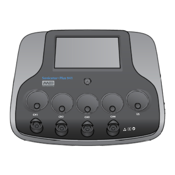
Page 16: Names Of Parts
Names of Parts ● Main Unit LCD touch panel Current intensity control dial (CH1) Current intensity control dial (CH2) Current intensity control dial (CH3) Current intensity control dial (CH4) ... - Page 17 Make sure the power switch for the Main Unit is turned off. Connect the power supply cord to the power supply cord connection port on the Main Unit. Connect the power supply cord to an AC power outlet. Select the electrode suitable for the treatment to be performed and the treatment area, then connect the electrode cable to the electrode cable connection port on the Main Unit.
-
Page 18: Preparations For Electrotherapy
Preparations for Electrotherapy ● Using the Self-adhesive Electrode Connect the electrode cable to the Self-adhesive Electrode. Insert the connection pins of the electrode cable into the cord for the corresponding parts of the Self-adhesive Electrode. * The electrode cable has two connection pins. Be sure to connect the two corresponding parts of the Insert each pin fully until you can Self-adhesive Electrode to the two pins. - Page 19 The Mettler Electronics is not skin. If there is any space between the Self- responsible for burns, equipment malfunctions, adhesive Electrode and the skin, simulation will...
- Page 20 Preparations for Electrotherapy ● Using HV/DC Probe * Do not use the HV/DC Probe in any mode other than Hi-Voltage, Galvanic, Diadynamic, Faradic, or Traebert mode. * When the HV/DC probe is connected, the output sets automatically to 1/10 (except for Hi-Voltage mode), and the open error detection function will be turned off.
- Page 21 [When using the Electrode Sponge (with slit) (optional)] When using the Electrode Sponge Electrode Sponge (with slit), slide it from the side so (with slit) that the steel plate of the circular electrode is enclosed by the sponge, then cover the steel plate with the folded-back sections of the felt.
-
Page 22: Display Of Electrotherapy Screen
Display of Electrotherapy Screen Treatment screen IF-2 Mode Time Carrier 9:51 IF.Freq. 9:51 10:00 10:00 10:00 30:00 0.00 W/cm 1 Treatment mode selection button This button is used to select electrotherapy mode or measurement mode. Touch the button to display the sub-window for selecting treatment mode. 2 Parameter setting buttons These buttons are used to set treatment parameters. - Page 23 stops and the treatment ends. 7 Output level display The output level of each channel is shown. The unit displayed will automatically switch according to the current output control. CC: mA, µA CV: V 8 Program load button This button is used to change the display to the load screen. * The button is inoperable for the channel in output operation.
-
Page 24: Operation For Electrotherapy
Operation for Electrotherapy * Make sure the electrodes that are used for the treatment are connected to the Main Unit and attached to the treatment area. Select the channel to use. Touch the appropriate channel selection button IF-2 and display the channel (CH1 to CH4) to use. Mode Time Carrier... - Page 25 Select the electrode to use. The icon displayed on the electrode selection button shows the connected electrode. * If an electrode that cannot be used for the selected treatment Carrier mode is connected, the electrode selection button indicates * Regarding the electrodes that can be used in each treatment mode, see pages 29 to 65.
- Page 26 Operation for Electrotherapy Pausing treatment To pause treatment, touch the pause button for the channel 9:51 in output operation. The output indication flashes and the output pauses. To resume the treatment, touch the pause button again or increase the output level by operating the intensity control dial.
-
Page 27: Setting Parameters For 4-Pole Interferential Mode
Setting Parameters for 4-Pole Interferential Mode Connectable Rubber Electrode, Self-adhesive Electrode (optional), electrodes Vacuum Electrode (optional) Usable channels Combination of CH1 and CH2 or combination of CH3 and CH4 Treatment screen Output mode setting button Timer setting button Carrier frequency setting button Interferential frequency setting button Vector sweep setting button... - Page 28 Setting Parameters for 4-Pole Interferential Mode Output mode setting When the output mode setting button is touched, a sub- window opens. Touch either (Constant) or (Sweep), then touch the OK button to close the sub-window. Timer setting When the timer setting button is touched, the up/down keys will appear to the right of the button.
- Page 29 When (Sweep) is selected as the output mode Touch the minimum frequency or maximum frequency indication. The selected numeric indication becomes highlighted, Sweep mode: Minimum and up/down keys will appear to the right of the button. frequency setting Set each frequency by using the up/down keys. Vector sweep setting Touch the vector sweep setting button and set the Sweep mode: Maximum...
-
Page 30: Setting Parameters For 2-Pole Interferential Mode
Setting Parameters for 2-Pole Interferential Mode Connectable Self-adhesive Electrode, Sponge Electrode, electrodes (optional) CH1 to CH4 Usable channels Treatment screen Output mode setting button Timer setting button Carrier frequency setting button Interferential frequency setting button... - Page 31 Output mode setting When the output mode setting button is touched, a sub- window opens. Touch either (Constant) or (Sweep), then touch the OK button to close the sub-window. Timer setting When the timer setting button is touched, the up/down keys will appear to the right of the button.
- Page 32 Setting Parameters for 2-Pole Interferential Mode When (Sweep) is selected as the output mode Touch the minimum frequency or maximum frequency indication. The selected numeric indication becomes highlighted, Sweep mode: Minimum frequency setting and up/down keys will appear to the right of the button. Set each frequency by using the up/down keys.
-
Page 33: Setting Parameters For Ems Mode
Setting Parameters for EMS Mode Connectable Self-adhesive Electrode, Sponge Electrode, electrodes (optional) Surge Independent: CH1 to CH4 Usable channels Surge Co-Cont, Surge Alternate: Combination of CH1 and CH2 or combination of CH3 and CH4 Treatment screen Output mode setting button Timer setting button Carrier frequency setting button Interferential frequency setting button... - Page 34 Setting Parameters for EMS Mode Output mode setting When the output mode setting button is touched, a sub- window opens. Touch (Surge Independent), (Surge Co- Cont), o (Surge Alternate), then touch the OK button to close the sub-window. * For Surge Co-Cont and Surge Alternate use two channels. : Simultaneous output from 2 channels : Alternating output from 2 channels Timer setting...
- Page 35 On/Off setting ≦ ≦ ≦ ≦ ≦ ≦ When the On/Off button is touched, a sub-window opens. Touch the item to change, and set the parameters using the up/down keys on the right side of the sub-window. ≦ ≦ ≦ On time setting button ≦...
-
Page 36: Setting Parameters For Russian Mode
Setting Parameters for Russian Mode Connectable Self-adhesive Electrode, Sponge Electrode, (optional) electrodes Independent: CH1 to CH4 Usable channels Co-Cont/Alternate: Combination of CH1 and CH2, or combination of CH3 and CH4 Treatment screen Output mode setting button Timer setting button Duty setting button On/Off setting button... - Page 37 Output mode setting When the output mode setting button is touched, a sub- window opens. Touch (Surge Independent), (Surge Co- Cont), o (Surge Alternate), then touch the OK button to close the sub-window. * For Surge Co-Cont and Surge Alternate use two channels. : Simultaneous output from 2 channels : Alternating output from 2 channels Timer setting...
- Page 38 Setting Parameters for Russian Mode On/Off setting ≦ ≦ ≦ ≦ ≦ ≦ When the On/Off button is touched, a sub-window opens. Touch the item to change, and set the parameters using the up/down keys on the right side of the sub-window. ≦...
-
Page 39: Setting Parameters For Hi-Voltage Mode
Setting Parameters for Hi-Voltage Mode Connectable Self-adhesive Electrode, Sponge Electrode, electrodes (optional), HV/DC Probe (optional) Constant, Sweep, Burst, Surge Independent: CH1 to CH4 Usable channels Surge Co-Cont, Surge Alternate: Combination of CH1 and CH2, or combination of CH3 and CH4 * When HV/DC Probes are connected, the open error detection function turns off. - Page 40 Setting Parameters for Hi-Voltage Mode Polarity/output mode setting When the polarity/output mode setting button is touched, a sub-window opens. Select the output mode by touching the (Constant), (Sweep), (Bur st), (Surge Independent) (Surge Co-Cont), or (Surge Alternate) button. Select the polarity from , or , then touch the OK button to close the sub-window.
- Page 41 On/Off setting (Surge mode only) ≦ ≦ ≦ ≦ ≦ ≦ When (Surge Independent), (Surge Co- Cont), o (Surge Alternate) is selected, the On/Off setting button appears. When the On/Off setting button is touched, a sub- window opens. ≦ ≦ Touch the item to change, and set the parameters using the up/down keys on the right side of the sub-window.
-
Page 42: Setting Parameters For Tens Mode
Setting Parameters for TENS Mode Connectable Self-adhesive Electrode, Sponge Electrode, (optional) electrodes Constant, Sweep, Burst, Surge Independent: CH1 to CH4 Usable channels Surge Co-Cont, Surge Alternate: Combination of CH1 and CH2, or combination of CH3 and CH4 Treatment screen Polarity/output mode setting button Timer setting button Frequency setting button Pulse duration setting button... - Page 43 Polarity/output mode setting When the polarity/output mode setting button is touched, a sub-window opens. Select the output mode by touching the (Constant), (Sweep), (Bur st), (Surge Independent) (Surge Co-Cont), or (Surge Alternate) button. Select (Symmetrical Waveform) or (Asym- metrical Waveform). * When symmetrical waveform is chosen, the polarity cannot be changed.
- Page 44 Setting Parameters for TENS Mode When selecting (Sweep) as the output mode Touch either minimum frequency or maximum frequency indication. The selected numeric indication becomes highlighted, Sweep mode: Minimum and up/down keys will appear to the right of the button. frequency setting Set each frequency by using the up/down keys.
- Page 45 Parameter setting range for TENS mode Output mode: Constant, Sweep, Burst, Surge Independent, Surge Co-Cont, Surge Alternate Waveform setting: Symmetrical waveform, asymmetrical waveform Polarity: positive, negative, alternate Frequency: Constant 0.5 to 250 Hz [0.5 Hz, 0.7 Hz, 1 to 10 Hz (1-Hz steps), 10 to 250 Hz (10-Hz steps)] Sweep 1 to 250 Hz [1 to 10 Hz (1-Hz steps), 10 to 250 Hz (10-Hz steps)] Burst 0.5 to 7 Hz [0.5, 0.7, 1 to 7 Hz (1-Hz steps)] Surge Independent, Surge Co-Cont, Surge Alternate 20 to 250 Hz (10-Hz steps)
-
Page 46: Setting Parameters For Microcurrent Mode
Setting Parameters for Microcurrent Mode Connectable Self-adhesive Electrode, Sponge Electrode, (optional) electrodes Usable channels CH1 to CH4 Treatment screen Phase 1 polarity setting button Phase 1 timer setting button Phase 1 frequency setting button Phase 2 polarity setting button Phase 2 timer setting button Phase 2 frequency setting button * In Microcurrent mode, electric currents of different settings can output continuously. - Page 47 Phase 1 polarity mode setting When the Phase 1 polarity setting button is touched, a sub-window opens. Select the Phase 1 polarity from , or , and touch the OK button to close the sub-window. * The set polarity applies to the gray connection pins of the electrode cable.
- Page 48 Setting Parameters for Microcurrent Mode Parameter setting range for Microcurrent mode Polarity: positive, negative, alternate Frequency: 0.2 to 400 Hz [0.2 Hz, 0.3 Hz, 0.5 Hz, 0.7 Hz, 1 to 10 Hz (1-Hz steps), 10 to 400 Hz (10-Hz steps)] Pulse duty: 50% (fixed) Timer: 1 to 60 minutes [1 to 30 minutes (1-minute steps), 30 to 60 minutes (5-minute steps), Phase 1 + Phase 2 ≤...
-
Page 49: Setting Parameters For Galvanic Mode
Setting Parameters for Galvanic Mode Connectable Sponge Electrode, (optional), HV/DC Probe (optional) electrodes Usable channels CH1 to CH4 * When HV/DC Probes are connected, output is automatically set to 1/10, and the open error detection function turns off. * When HV/DC Probes are connected, CV is automatically set. CC cannot be selected. Treatment screen Polarity/output mode setting button Timer setting button... - Page 50 Setting Parameters for Galvanic Mode Polarity/output mode setting When the polarity/output mode setting button is touched, a sub-window opens. Select (Positive/Continuous), (Negative/ Continuous), (Positive/Interrupted), or (Negative/Interrupted), and touch the OK button to close the sub-window. * The set polarity applies to the gray connection pins of the electrode cable.
- Page 51 Parameter setting range for Galvanic mode Output mode: Continuous, Interrupted Polarity: positive, negative Pulse duration (interrupted): 60 ms, 100 ms, 300 ms, 500 ms, 1000 ms (pulse duty fixed at 95%) Frequency (interrupted): 0.95 to 15.8 Hz Timer: 1 to 60 minutes [1 to 30 minutes (1-minute steps), 30 to 60 minutes (5-minute steps)] Output current (peak current value): 0.2 to 20 mA (0.2-mA steps) Output voltage (peak voltage value at 500 Ω...
-
Page 52: Preparing For Ultrasound Therapy
2. MULTIPLE SOCKET-OUTLET or extension cord shall not be connected to the SONICATOR PLUS 941. 1. In order to disconnect from a wall socket, pull the plug. CAUTION 2. Do not position the SONICATOR PLUS 941 so that it is difficult to... - Page 53 To avoid electric shock, do not perform any operations other than the WARNING operation of the Ultrasound Probe when your hands are wet. Caution regarding auto contact function ● The auto contact function adjusts output to minimum levels when the Ultrasound Probe is moved away from the treatment area (skin) but does not completely shut off output.
-
Page 54: Ultrasound Therapy Screen
Ultrasound Therapy Screen Treatment screen ultrasound Freq. Time Duty 29:51 Pulse Freq. 20:00 29:51 20:00 20:00 20:00 1.00 W/cm 1 Treatment mode selection button This button is used to select the treatment mode for ultrasound therapy or combination therapy. Touch the button to display the sub-window for selecting treatment mode. 2 Parameter setting buttons These buttons are used to set ultrasound therapy parameters. - Page 55 6 Pause button This button appears during output operation only. It is used to pause, resume, or stop output. When the pause button is touched, the output pauses. When the button is touched again, the output resumes. When the pause button is pressed and held, the output stops and the treatment ends. 7 Output level display The output level is shown.
-
Page 56: Operation For Ultrasound Therapy
Operation for Ultrasound Therapy Connectable Ultrasound Probe (L), Ultrasound Probe (S) (optional) electrodes US only Usable channels * Make sure the Ultrasound Probe to be used is connected to the Main Unit. Select the US channel. ultrasound Touch the ultrasound channel selection button to Duty Freq. - Page 57 Set the frequency. Touch the frequency setting button to set the ultrasound Freq. frequency. Touch the button to toggle between “1 MHz” and “3 MHz.” Set the timer. When the timer setting button is touched, up/down Time keys will appear to the right of the button. 30:00 Set the treatment time by using the up/down keys.
- Page 58 Operation for Ultrasound Therapy Apply ultrasound gel to the applicator. * When using ointment as the ultrasound coupler, select OTM with the GEL/OTM setting button on the setting screen/treatment setting. For information on GEL/OTM settings, see page 99. Start output. Turn the ultrasound intensity control dial to the right to increase output and start treatment.
- Page 59 When the timer reaches “00:00,” the end melody rings and the output stops. *There will be no end melody if the sound level setting is set to Mute. For information on setting end melody, see page 98. Turn off the power switch for the Main Unit. Wipe off ultrasound gel from the applicator and disconnect the Ultrasound Probe from the Main Unit.
-
Page 60: Preparing For Combination Therapy
Preparing for Combination Therapy Make sure the power switch for the Main Unit is turned off. Connect the power supply cord to the power supply cord connection port on the Main Unit. Connect the power supply cord to an AC power outlet. - Page 61 Attach the electrode securely close to the treatment area. Connect the electrode cable to the electrode cable connection port for CH4. * Only the combination of CH4 and US channels can be used in Combination mode. Connect one of the Ultrasound Probe (L) and Ultrasound Probe (S) (optional), or both to the Ultrasound Probe connection port.
-
Page 62: Combination Therapy Screen
Combination Therapy Screen Treatment screen 1 Treatment mode selection button This button is used to select ultrasound therapy mode or combination therapy mode. Touch this button to display a sub-window for selecting a treatment mode. 2 Electrotherapy parameter setting area This area is used to set treatment parameters for electrotherapy. - Page 63 6 Pause button This button appears only for the channel in output operation. It is used to pause, resume, or stop the output from each channel. When the pause button is touched, the output from the corresponding channel pauses. When the button is touched again, the output resumes. When the pause button is pressed and held, the output from the corresponding channel stops and the treatment ends.
-
Page 64: Operation For Combination Therapy
Operation for Combination Therapy Electrotherapy: Self-adhesive Electrode, SpongeElectrode, Connectable (optional), electrodes Ultrasound therapy: Ultrasound Probe (L), Ultrasound Probe (S) (optional) Usable channels Combination of CH4 and US only * Make sure the electrode used is connected to the Main Unit or the Vacuum Unit (optional) and attached to the treatment area. - Page 65 Set the treatment parameters for electrotherapy. The parameters that can be set depend on the treatment mode set. * Surge Independent, Surge Co-Cont, and Surge Alternate modes for Hi-Voltage and TENS cannot be used for combination therapy. * For information on setting electrotherapy parameters, see pages 29 to 61.
- Page 66 Operation for Combination Therapy Start ultrasound output. Turn the ultrasound intensity control dial to the right to increase output and start treatment. When output starts, the LED around the ultrasound intensity control dial will light up. * A treatment melody will ring during output operation. There will be no treatment melody if the treatment melody is set to mute.
- Page 67 To end treatment To stop treatment, either press and hold the pause button or set the ultrasound intensity control dial to “0” or press the stop switch. * When the stop switch is pressed, all channels in output operation stop. When the timer reaches “00:00,”...
-
Page 68: Display Of Clinical Program Screen
Display of Clinical Program Screen Clinical program selection screen 1 Upper-/lower-body selection button This button is used to change the treatment area of the body. Press the button to toggle between the upper body and lower body. 2 Treatment area selection buttons These buttons are used to select the treatment area. - Page 69 Treatment guidance screen 1 Treatment point display This screen area shows treatment points. Blue or green square: This indicates the electrode attachment position for electrotherapy. If the polarity is set, a “+” or “-” sign is also indicated. When two channels are used, the squares are displayed in different colors to make it possible to distinguish channels.
-
Page 70: Operation Of Clinical Program
Operation of Clinical Program Clinical programs are reference examples and should not be considered the most suitable programs for specific indications. CAUTION When performing a treatment, qualified persons should determine the program based on the patient’s condition and symptoms. * Make sure the electrode and Ultrasound Probe used are connected to the Main Unit. Select the channel to be used. - Page 71 Select the treatment program. After the treatment area is selected, the right half of the screen will display the names of clinical programs based on the treatment area selected. Touch the desired treatment program from the programs available for the indications to be treated. The display changes to the treatment guidance screen.
-
Page 72: Saving Programs
Saving Programs Up to 10 programs can be saved for each treatment mode (except for I/T Measurement mode and AQ Measurement mode). Select a channel. Touch the channel selection button to display the channel for which the parameters to be saved are set. - Page 73 To rename a program Touch the edit button in the program save sub- window to change the display to the program name editing screen. Use the keyboard to rename the program. Touch OK to confirm the change and to return to the sub- window.
-
Page 74: Loading Programs
Loading Programs Select the channel. Touch the channel selection button to display the channel for which a previously saved program is to be loaded. Display the loading screen. Touch the program load button to display the sub-window. Time Select the program number of the program to be loaded. - Page 75 The program number display. After the program is loaded, the display returns to the treatment screen. Confirm that the program load button indicates the program number of the loaded program. * If any parameters in the loaded program have changed, the color of the program number display will change.
-
Page 76: Setting Screen
Setting Screen Screen/Sound screen Config. Screen/Sound US Indication Language Key sound Error sound Brightness End melody Treatment melody Contact sound ≦ Initialization 1 Brightness setting buttons These buttons are used to set screen brightness. 2 Key sound setting button This button is used to set the volume of the key sound. [Sound level setting sub-window] Touch this button to display a sound level setting sub-window. - Page 77 9 Contact sound level setting button This button is used to set the volume of the contact sound. Touch this button to display a sound level setting sub-window. 10 Initialization button This button returns settings and all program content to factory set conditions. 11 OK button This button finalizes the settings and returns the display to the treatment screen.
- Page 78 Setting Screen Language screen Config. Screen/ Sound US Indication Language Francais English Deutsch Italiano Portugues Espanol Tieng Viet TOrkce Initialization 1 Language setting button These buttons are used to select the language of the display. Set the language to any of the following nine languages: English, German, French, Italian, Spanish, Portuguese, Turkish, Vietnamese, or Chinese 2 Initialization button This button returns settings and all program content to factory set conditions.
-
Page 79: Error Screen
Error Screen ● Error 1: Open error Error 1 This error is displayed if the electrode or Ultrasound Probe is disconnected from the Main Unit or if the electrode detaches from the treatment area. If this error occurs, connect the electrode or Ultrasound Probe securely to the Main Unit. -
Page 80: Emc
●HV/DC Probe: 2.09 m ●Power Supply Cord: 2.44 m ● Using accessory products other than replacement parts sold by the Mettler Electronics may increase product emissions and decrease immunity. ● Avoid using the product when it is placed next to or on top of other equipment. If the product must be placed next to or on top of other equipment, make sure the product and other equipment function properly before use. - Page 81 Guidance and manufacturer’s declaration — electromagnetic immunity This unit is intended for use in the electromagnetic environment specified below. The customer or the user of this unit should assure that it is used in such an environment. IEC 60601-1-2 compliance Electromagnetic environment Immunity test test level...
- Page 82 Guidance and manufacturer’s declaration — electromagnetic immunity This unit is intended for use in the electromagnetic environment specified below. The customer or the user of this unit should assure that it is used in such an environment. IEC 60601-1-2 compliance Electromagnetic environment Immunity test test level...
- Page 83 Recommended separation distances between portable and mobile RF communications equipment and this unit This unit is intended for use in an electromagnetic environment in which radiated RF disturbances are controlled. The customer or the user of this unit can help prevent electromagnetic interference by maintaining a minimum distance between portable and mobile RF communications equipment (transmitters) and this unit as recommended below, according to the maximum output power of the communications equipment.
- Page 84 1333 South Claudina Street • Anaheim, CA 92805, U. S. A. Toll Free: (800) 854–9305 • Telephone: (714) 533–2221 • FAX: (714) 635–7539 Web Site: http://www.mettlerelectronics.com • Email: mail@mettlerelectronics.com...
Need help?
Do you have a question about the Sonicator Plus 941 and is the answer not in the manual?
Questions and answers