Table of Contents
Advertisement
®
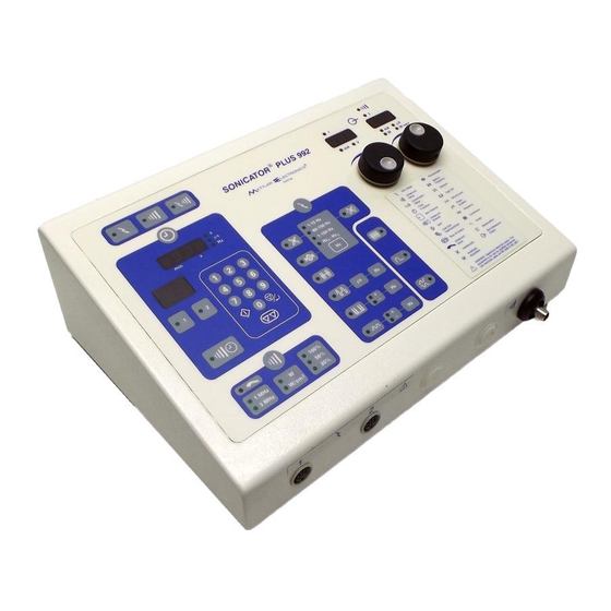
Sonicator
Plus 992
Maintenance Manual
®
1333 South Claudina Street • Anaheim, CA 92805, U. S. A.
US Toll Free: (800) 854–9305 • Telephone: 1 (714) 533–2221 • FAX: 1 (714) 635–7539
Mettler Electronics' World Wide Web Site: http://www.mettlerelec.com
IR7–95
April, 1999
Copyright © 1999 by Mettler Electronics Corp.—Anaheim, CA
Advertisement
Table of Contents

Subscribe to Our Youtube Channel
Related Manuals for Mettler Electronics Sonicator Plus 992


Summary of Contents for Mettler Electronics Sonicator Plus 992
- Page 1 1333 South Claudina Street • Anaheim, CA 92805, U. S. A. US Toll Free: (800) 854–9305 • Telephone: 1 (714) 533–2221 • FAX: 1 (714) 635–7539 Mettler Electronics’ World Wide Web Site: http://www.mettlerelec.com IR7–95 April, 1999 Copyright © 1999 by Mettler Electronics Corp.—Anaheim, CA...
- Page 2 Mettler Electronics Corp.
-
Page 3: Table Of Contents
Sonicator Plus 992 Maintenance Manual Table Of Contents Section Title Page Introduction Symbol Glossary and List of Abbreviations Symbol Glossary Treatment Status Indicator Icons List of Abbreviations Specifications General Specifications Ultrasonic Generator Specifications Ultrasonic Applicator Specifications Waveform Specifications Amplitude Modulation Specifications... - Page 4 High Volt Waveform 3.13 Microcurrent Waveform Sonicator Plus 992 Block Diagram Sonicator Plus 992, Rear view, Mains Power Switch and Line cord connections Sonicator Plus 992, Front View—Electrode Cable and Ultrasound Applicator Connections Connecting the Applicator to the Universal Applicator Cable...
-
Page 5: Introduction
Sonicator Plus 992 servicing should be done at the factory. If it is not possible to return the Sonicator Plus 992 to the factory, this service manual may be used to troubleshoot to the major subassembly level. Discrepant subassemblies can then be repaired by ordering them from the factory as an alternative to returning the complete system. - Page 6 Mettler Electronics Corp.
-
Page 7: Symbol Glossary And List Of Abbreviations
Sonicator Plus 992 Maintenance Manual Section 2—Symbol Glossary and List of Abbreviations Symbol Glossary Electrical Stimulation Selector Therapeutic Ultrasound Selector Combination Therapy Selector Time display 1 5. 0 0 Time display LED’s. Displays treatment time and numeric values for frequency, phase duration, on/off times and alphanumeric error codes. -
Page 8: High Volt Waveform
Mettler Electronics Corp. Frequency selector for 5 cm² 1 and 3 MHz applicator. Displays frequency for 1 MHz all applicators. 3 MHz Ultrasound output display selector W/cm² Ultrasound duty cycle selector 100% Interferential waveform selector—LED is illuminated when this function is activated. -
Page 9: Treatment Status Indicator Icons
Sonicator Plus 992 Maintenance Manual Reciprocation selector, use for channel pair 1 & 2 Stimulation or ultrasound output displays 0 0 0 LED’s that display the output intensity during a treatment. When the unit is in the “Hold” mode for electrical stimulation, or ultrasound for CE models, “--- ---“... -
Page 10: Biphasic (Tns) Waveform
Mettler Electronics Corp. Ultrasound selected Combination therapy selected, waiting for waveform type to be selected. Interferential waveform selected. Display will move to the right when the outputs are active. Interferential vector rotation control selected. Display appears to rotate. Premodulated waveform selected. Display will move to the right when the outputs are active. -
Page 11: List Of Abbreviations
Sonicator Plus 992 Maintenance Manual High volt waveform selected for combination therapy. Display will move to the right when the outputs are active. Microcurrent waveform selected. Display will move to the right when the outputs are active. List of Abbreviations cm²... - Page 12 Mettler Electronics Corp.
-
Page 13: Specifications
General Specifications: Input: 90–240 VAC, 50–60 Hz, 2.3 Amp. Nom. Certification: The Sonicator Plus 992 complies with the ultrasound Domestic model performance standards set forth in the Code of Federal Regulations, Title 21 (Food and Drugs), Part 1050.10 and IEC 601-2-5, 1 Ed., 1984... -
Page 14: Ultrasonic Generator Specifications
Mettler Electronics Corp. Treatment Timer: Treatment time counts down to zero when a time is set, or up to 60 or 30 minutes when no time is set. The digital timer indicates time in minutes and seconds. The timer also indicates the remaining or elapsed treatment time during the “Hold”... -
Page 15: Ultrasonic Applicator Specifications
Sonicator Plus 992 Maintenance Manual In the continuous mode, the power is on at least 95% of the time the timer is running. The continuous mode waveform is shown below: Output 1, 3.2 or 3.3 MHz Ultrasound Time Figure 3.3—Continuous Waveform... - Page 16 Mettler Electronics Corp. Figure 3.5—5 cm² Applicator (1 MHz), ME 7513,—Three Dimensional Beam Pattern Figure 3.6—5 cm² Applicator (3.2 MHz), ME 7513,—Three Dimensional Beam Pattern Figure 3.7—1 cm² Applicator (3.3 MHz), ME 7331,—Three Dimensional Beam Pattern...
-
Page 17: Waveform Specifications
Sonicator Plus 992 Maintenance Manual Waveform Specifications: Interferential Mode Waveform Type: Sinewave Polarity: None Volts: 0–65 volts RMS, 1 Kohm load Current: 0–65 mA RMS, 1 Kohm load Average current at maximum intensity and frequency: 65 mA RMS Maximum current density under 2"... - Page 18 Mettler Electronics Corp. Medium Frequency Mode Waveform Type: Burst modulated sine wave Polarity: None Volts: 0–50 volts RMS, 1 Kohm load Current: 0–50 mA RMS, 1 Kohm load Average current at maximum intensity and frequency: 50 mA RMS Maximum current Figure 3.10—Medium...
- Page 19 Sonicator Plus 992 Maintenance Manual High Volt Mode Waveform Type: Monophasic twin peak Polarity: Positive or negative 500 volts 8 us Volts: 500 volts peak, 1 Kohm load Current: 0–500 mA peak, 1 Kohm load 50 % Average current at...
-
Page 20: Amplitude Modulation Specifications
Mettler Electronics Corp. Amplitude Modulation Specifications: Vector rotation: Interferential Mode Only -50% amplitude modulation in anti phase with an eight second modulation period. Surge Mode: Premodulated, Medium Frequency and Biphasic (TNS) Pulsed Modes Up ramp: 3 seconds Down ramp: 2 seconds... -
Page 21: Precautions
4. Adhere to standard safety practices for troubleshooting and servicing electronic equipment. 5. To insure continued conformance to specifications and applicable safety standards, the Sonicator Plus 992 should be performance checked and safety tested at least once each year. 6. USE OF CONTROLS OR ADJUSTMENTS OR PERFORMANCE OF PROCEDURES OTHER THAN THOSE SPECIFIED HEREIN MAY RESULT IN HAZARDOUS EXPOSURE TO ELECTRICAL ENERGY. - Page 22 Mettler Electronics Corp.
-
Page 23: Equipment Description
Phillips head screws. There are two printed circuit boards in the Sonicator Plus 992: the main circuit board with the displays and the power supply board. The power supply board holds the two primary fuses. Each of these subassemblies is described in the Theory of Operation section of this manual. - Page 24 Mettler Electronics Corp.
-
Page 25: Theory Of Operation
Sonicator Plus 992 Maintenance Manual Section 6—Theory of Operation The Sonicator Plus 992 is a sophisticated microprocessor controlled, variable frequency, variable amplitude, multi-channel muscle stimulation signal and ultrasound output generator. It takes line voltage, which is transformed down to lower voltages and converts this voltage to regulated DC voltages, which are used internally for powering the circuitry. -
Page 26: Sonicator Plus 992 Block Diagram
Sonicator Plus 992 System Block Diagram Input Line Filter Receptacle Assembly Power Membrane Switch Cord Panel Ultrasound Output Connector Main Power Board Supply Assembly Channel 2 Stimulation Output Connector Channel 1 Stimulation Output Connector Figure 6.1—Sonicator Plus 992 Block Diagram... -
Page 27: Installation Instructions
Section 7—Installation Installation Instructions 1. Connect the line cord to the back of the Sonicator Plus 992. (See Figure 7.1) 2. Plug the line cord (ME 7293, domestic model or ME 7296, CE model) into a grounded wall outlet that is rated between 90–240 VAC, 50–60 Hz. Your power supply must match the voltage requirements listed on the serial number label of your device. -
Page 28: Sonicator Plus 992, Front View-Electrode Cable And Ultrasound Applicator
Mettler Electronics Corp. Mains Power Switch Applicator Clamp Line Cord Connection Figure 7.1— Sonicator Plus 992, Back View— Mains Power Switch, Line Cord Connection and Applicator Clamp Applicator Cable Connection Electrode Cable Connections Figure 7.2— Sonicator Plus 992, Front View—... -
Page 29: Operating Instructions
Figure 8.1—Front membrane panel and LED indicators A Note about Electrodes To ensure safe operation of the Sonicator Plus 992, follow the recommendations listed below: 1. We strongly encourage careful maintenance of the electrode system. This includes the lead wires as well as the pads themselves. Worn cables and/or poor pads (or the wrong sized pads) can have a significant impact upon treatment results. -
Page 30: General Operating Instructions
General Set-up Procedure Turn on the mains power switch by pressing “I” icon on switch. When you first turn the Sonicator Plus 992 on, the LED’s for treatment selectors will flash. NOTE: This is how you will know what your choices are when setting up a treatment. -
Page 31: Stimulation Set-Up Procedure
11. Use this button to stop the treatment output that is currently being displayed by the Sonicator Plus 992. All treatment parameters will still be as you programmed them. For ultrasound, the output intensity will also be remembered. For stimulation, you will be required to readjust the output intensity starting at zero if you resume treatment. - Page 32 Medium Frequency— No optional selections Biphasic (TNS)— µs The Sonicator Plus 992 stores the value for the phase duration and the frequency for the last Biphasic (TNS) session. If the value displayed in the timer window is acceptable press the key.
- Page 33 Sonicator Plus 992 Maintenance Manual lead wire’s polarity. Set Hz for the frequency, 1-120 Hz. Enter a numeric value followed by the key. Microcurrent— – Set the treatment polarity. The LED that is lit indicates the red lead wire’s polarity. Pressing the button twice will allow the polarity to alternate in a biphasic manner.
-
Page 34: Ultrasound Set-Up Procedure
Mettler Electronics Corp. Surge + Reciprocation— Press Reciprocation key. Press the key. Press the Surge key until you see the On/Off time you want to use. Press the key. 1 5. 0 0 Enter the treatment time using the numeric keypad. The µs... - Page 35 Sonicator Plus 992 Maintenance Manual The green LED indicator will illuminate for the ultrasound treatment. Indicators will blink for channels that have already been programmed, but are not being programmed currently. To view the parameters for a channel, whose indicators are blinking, press the selector button.
- Page 36 LED in the symbol pictured to the left will blink. If inadequate coupling occurs for more that 30 continuous seconds, 6 continuous seconds for CE model, the Sonicator Plus 992 will automatically stop ultrasound output, beep twice and display “E002” in the time display.
-
Page 37: Combination Therapy Set-Up Procedure
Sonicator Plus 992 Maintenance Manual Combination Therapy Set-up Procedure Press the combination treatment selector. The Treatment Status Indicator will show you the combination icon and the waveform LED’s for Premodulation, Medium Frequency, Biphasic (TNS) and High Volt will begin to blink. - Page 38 Medium Frequency— No optional selections Biphasic (TNS)— µs The Sonicator Plus 992 stores the value for the phase duration and the frequency for the last Biphasic (TNS) session. If the value displayed in the timer window is acceptable press the key.
-
Page 39: Electrode Positioning
Electrodes should never be placed in such a manner as to produce current flow through the cardiac area. For safe operation of the Sonicator Plus 992, review contraindications, warnings, precautions and Side Effects/Adverse Reactions in sections 5.4, 5.5, 5.7 and 5.8 before... -
Page 40: Quadpolar Electrode Placement Technique
Mettler Electronics Corp. positioning electrodes. 2. Preparation of the skin prior to electrode application To insure the efficient current conduction necessary for proper treatment, certain preparations must be made. Cleaning or wetting should eliminate any impairment to current conduction on the patient’s skin such as an oily or dry surface, or excessive hair coverage. -
Page 41: Using The Pencil Electrode
Sonicator Plus 992 Maintenance Manual distal to the active electrode. The dispersive pad is generally three Technique to four times larger than the active electrode so that current density is too low to cause muscle contractions under the dispersive electrode. Never place the dispersive electrode over the antagonist muscle. - Page 42 Mettler Electronics Corp.
-
Page 43: Maintenance And Troubleshooting
Troubleshooting Cleaning the Sonicator Plus 992 The Sonicator Plus 992 can be wiped off with a damp cloth. The power cord should be disconnected from the unit before this is done. In the case of stubborn dirt a gentle household cleaner can be sprayed on the cloth and then wiped on the unit. If this method is used, remove any cleaner residue with a damp cloth. - Page 44 Resume treatment after applying proper couplant. Replace applicator. 4. “E003” displayed in Time window. The Sonicator Plus 992 cannot tune to the applicator transducer. Turn unit off and then on and try to begin another ultrasound treatment. If the error code persists, the applicator and/or the Sonicator Plus 992 require servicing.
- Page 45 If problem is not addressed above, or if additional troubleshooting guidance is desired, call (800) 854-9305 or 1-714-533-2221 (outside the USA). The distributor who sold the Sonicator Plus 992 should be able to assist you with a loaner unit during warranty service.
- Page 46 Mettler Electronics Corp.
-
Page 47: Test And Calibration Procedure
Section 10— Test and Calibration Procedure The following procedure is used to verify that all functions of the Sonicator Plus 992 are performing to product specifications. This procedure should be performed whenever a main board is replaced or when there is any question about the performance of the unit. -
Page 48: Diagnostic Tests
Mettler Electronics Corp. Main Bd: Power Up Check Turn power on. The timer display should show “----”. The output displays should show “---”. The 3 treatment LED’s should flash. 10.3 Diagnostic Tests Enter Diagnostic Mode Press the Continuous key and turn power on. The timer display will show dd00. - Page 49 Sonicator Plus 992 Maintenance Manual Press the 2 key. Monitor the high end of the 1 MHz VCO sweep frequency at TP1 on the Main Bd. Adjust it to 6.420 MHz by turning the Channel 1 output knob on the front panel.
-
Page 50: Ultrasound Output Tests
Mettler Electronics Corp. Exit Diagnostic Mode Turn power off, and then back on. 10.4 Ultrasound Output Tests Output Waveforms Connect a 10x1 applicator to the unit with a BNC "T" connector. Connect a 10x-scope probe to the BNC connector. Place the applicator in the ultrasound wattmeter. Zero the wattmeter. -
Page 51: Ultrasound Error Tests
Sonicator Plus 992 Maintenance Manual 10.5 Ultrasound Error Tests Error 1: No Applicator Connected Press Go. Disconnect the 10x1 applicator from the unit. The unit should beep twice, stop the treatment, and display E001. Reconnect the applicator. Treatment time remaining should be displayed. - Page 52 Mettler Electronics Corp. Stop the treatment. Set 4250 Hz on Channel 2. Restart the treatment. Adjust to 20 ma. Record the frequency. s/b 4243 ± 3 Hz Stop the treatment. Set Channel 2 to sweep from 1 to 150 Hz. Restart the treatment.
- Page 53 Sonicator Plus 992 Maintenance Manual Adjust the displayed current to 50 ma. Record the actual current of both channels. s/b 50 ± 10 ma Stop the treatment. Medium Frequency Output Tests: Put the unit in Medium Frequency Mode. Start the treatment.
- Page 54 Mettler Electronics Corp. Adjust the displayed current to 90 ma. Record the positive and negative voltages of both channels. s/b 90 ± 18 volts Adjust the displayed current to 99 ma. Record the positive and negative voltages of both channels. s/b 99 ± 20 volts Stop the treatment.
-
Page 55: Stimulation Recip And Surge Tests
Sonicator Plus 992 Maintenance Manual 10.7 Stimulation Recip and Surge Tests Surge Tests—Single Timer: Put Channel 1 & 2 in Premodulated mode, 1-15 Hz sweep. Put Channel 1 & 2 in Surge, 2 sec on, and 3 sec off. Start the treatment. Adjust both channels for 20 ma. -
Page 56: Eeprom Memory Test
Mettler Electronics Corp. Replace the load in Channel 2. Verify E 07 clears. Repeat steps above in Biphasic (TNS) mode, 150 us, 80 Hz. Error 8—Over Current Error Put the unit in Medium Frequency mode. Start the treatment. Adjust Channel 1 for 20 ma. -
Page 57: Burn-In
Sonicator Plus 992 Maintenance Manual 10.12 Burn-In This procedure is performed after replacing any chassis component or circuit board. Turn power off. Seal the three pots. Complete final assembly. Install 1 K loads on both channels. Connect the 10x1 applicator. -
Page 58: Final Operational Check
Mettler Electronics Corp. 10.15 Final Operational Check Connect unit to nominal power. Connect 10x1 applicator. Start US treatment Verify output accuracy at 20 W. Start Interferential treatment on Channels 1 & 2. Verify output accuracy at 30 ma. -
Page 59: Parts Replacement
Sonicator Plus 992 Maintenance Manual Section 11 — Parts Replacement 11.1 Chassis Disassembly If an analysis of the error codes or the unit’s operation suggests that it is necessary to replace an internal chassis component perform the procedures described below. -
Page 60: Chassis Top Components Servicing
Mettler Electronics Corp. Line Power Switch Replacement Note the location and order of connection of the brown and blue wires connected to the power switch. There are two brown wires on the left side of the switch from top to bottom and there are two blue wires on the right side of the switch. - Page 61 Sonicator Plus 992 Maintenance Manual socket driver, remove the five standoffs that are screwed to the board taking careful note of their location. Remove the remaining Phillips head screws that mount the board. Lift the board out and away from the chassis.
- Page 62 Mettler Electronics Corp.
-
Page 63: Parts
Sonicator Plus 992 Maintenance Manual Section 12—Parts List Part Number Part Description QT3-02 Main Board Assembly HH3-01 Power Supply Board Assembly FA1-11 Fuse, 5 x 20mm, 4A WKR9-00 Case Top HG1-22 Membrane Switch PA7-91 Label, Output Jack PA7-88 Label, Nomenclature... - Page 64 Mettler Electronics Corp.
-
Page 65: Accessories
For information regarding either Mettler products or a distributor near you, please call toll free, (800) 854–9305 or phone (714) 533–2221 in areas outside the continental United States. Ask for Customer Service. Mettler Electronics is open from 7 AM until 5 PM Pacific Time for your convenience. - Page 66 Hooded, water-proof universal applicator cable for the Sonicator Plus 992 and 994 7513 Sonicator Plus 992 and 994 applicator (5 cm²/ 1 or 3.2 MHz) Deluxe mobile therapy cart Slanted bracket accessory for ME 93 cart to mount one additional Sonicator or Sys * Stim unit on the ME 93 cart pedestal.
- Page 67 4 PPM (dissolved oxygen) for reliable results and adherence to FDA measurement requirements. Mettler Electronics Corp. developed a good method for degassing water using a canning technique involving a pressure cooker and Mason jars. This is easier than boiling water for 30 minutes and transferring it to plastic bottles while still hot, then placing the bottles in a refrigerator.
- Page 68 Mettler Electronics Corp. Appendix B Ultrasound Applicator Repair 1. Figure B.1 shows the ME 7513 applicator top assembly. It is representative of all the Sonicator 992 applicators. 2. Applicator components include: transducer ring assembly and handle assembly. 3. Replacement crystal ring and applicator handle assemblies may be installed by Mettler authorized repair facilities only.
- Page 69 Sonicator Plus 992 Maintenance Manual Appendix C Result Codes for Keyboard Test: US Timer Surge W:W/cm Interferential 25 Premodulated 26 Medium Freq 27 Biphasic (TNS)28 High Volt Micro Current 30 Sweep Hold Rotate Stop exits Bip uS Stim Bip Hz...
- Page 70 Mettler Electronics Corp.
Need help?
Do you have a question about the Sonicator Plus 992 and is the answer not in the manual?
Questions and answers