Table of Contents
Advertisement
Please, read this manual
before use!
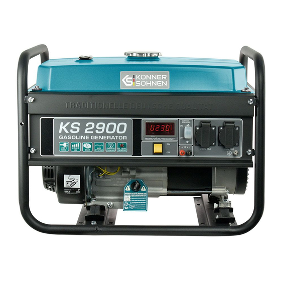
Gasoline generator
KS 2900
KS 3000
KS 3000E
KS 7000
KS 7000E
KS 7000E-3
KS 7000E ATS
Dual fuel generator
KS 2900G
KS 3000G
KS 3900E G
KS 5000E G
K S
&
Instruction
KS 7000E-3 ATS
KS 7000E 1/3
KS 10000E 1/3
KS 10000E
KS 10000E-3
KS 10000E ATS
KS 10000E-3 ATS
KS 7000E G
KS 9000E G
KS 10000E G
K ö n n e r
K S
h n e n
&
&
ö
S
ENG
Advertisement
Table of Contents


Need help?
Do you have a question about the KS 2900 and is the answer not in the manual?
Questions and answers