Table of Contents
Advertisement
Advertisement
Table of Contents

Related Manuals for K&S KS 4000iE S


Summary of Contents for K&S KS 4000iE S
- Page 1 Owner’s Manual Please, read this manual carefully before use! Inverter Generator KS 1200i KS 2100i KS 3500i KS 3500iE G-Profi KS 7100iE G-Profi Inverter Generator in Soundproof Housing KS 2000i S KS 3300i S KS 3300iEG S-Profi KS 4000iE S...
-
Page 2: Table Of Contents
3. SAFETY SYMBOLS 4. DESCRIPTION OF GENERATOR INSCRIPTIONS 5. OVERVIEW AND COMPONENTS OF INVERTER GENERATORS KS 1200i, KS 2100i 6. OVERVIEW AND COMPONENTS OF INVERTER GENERATOR KS 2000i S 9-10 7. OVERVIEW AND COMPONENTS OF INVERTER GENERATORS KS 3300i S, KS 3300iEG S-Profi 11-12 8. -
Page 3: Preface
1. PREFACE Congratulations on your purchase of the gasoline generator from TM Könner & Söhnen. This manual contains safety instructions, a description of the use and commissioning of Könner & Söhnen generators and procedures for their maintenance. The generator manufacturer may make some modifications that may not be reflected in this manual. -
Page 4: Inverter Generator Use And Safety Precautions
2. INVERTER GENERATOR USE AND SAFETY PRECAUTIONS Read this manual carefully before starting to use the generator. WORK AREA - Do not use the generator near flammable gases, liquids or dust. During operation of the generator, its exhaust system becomes very hot. This may cause fire or explosion of these materials. - Page 5 PERSONAL SAFETY -Safety first! Do not operate the generator when you are tired or under the influence of potent drugs, alcohol or medication. During operation, inattention can cause serious injury. - Do not wear loose clothing or jewelry while operating the generator. Long hair, loose clothing as well as jewelry could get caught in the rotating parts of the generator and result in injury.
-
Page 6: Safety Symbols
3. SAFETY SYMBOLS DESCRIPTION OF SAFETY SYMBOLS WHEN OPERATING THE GENERATOR a. Be careful when operating the device! Observe f. Read this owner’s manual carefully before the safety instructions in this manual. operating the device. b. Operate the generator only in well-ventilated g. -
Page 7: Description Of Generator Inscriptions
4. DESCRIPTION OF GENERATOR INSCRIPTIONS APART FROM THE SAFETY SYMBOLS, THE GENERATOR CONTAINS THE FOLLOWING INSCRIPTIONS: Specifications table. Specifications vary with the model. For more information, see “Generator Specifications”. Noise level is indicated. The noise level varies with the model. For more information, see “Generator Specifications”. -
Page 8: Overview And Components Of Inverter Generators
5. OVERVIEW AND COMPONENTS OF INVERTER GENERATORS KS 1200i, KS 2100i Fig.. 1 1. Carrying handle 5. Manual starter 2. Fuel tank cap 6. Air choke control knob 3. Control panel 7. Air filter 4. Fuel valve 8. Engine KS 1200i CONTROL PANEL Fig. - Page 9 KS 2100i CONTROL PANEL Fig. 3 1. Overload indicator (red) 6. Ground terminal 2. Voltage indicator (green) 7. 12V/5A DC outlet 3. Oil level indicator (yellow) 8. DC fuse 4. Engine start button (ON/OFF) 9. 2x16А AC outlets 5. Economy control switch (ЕCОN) PLEASE NOTE! The manufacturer reserves the right to make changes in the product design, configuration and construction.
-
Page 10: Overview And Components Of Inverter Generator Ks 2000I S
6. OVERVIEW AND COMPONENTS OF INVERTER GENERATOR KS 2000i S Fig. 4 1. Fuel tank cap 3. Plug service cover 2. Carrying handle 4. Control panel 5. Service cover 8. Vent grid 6. Manual starter 9. Damper 7. Fuel valve... - Page 11 KS 2000i S CONTROL PANEL Fig. 5 1. Overload indicator (red) 6. Engine start button (ON/OFF) 2. Voltage indicator (green) 7. 12V/8A DC outlet 3. Oil level indicator (yellow) 8. 12V DC fuse 4. Economy control switch (ЕCОN) 9. 2x16А AC outlets 5.
-
Page 12: Ks 3300I S, Ks 3300Ieg S-Profi
7. OVERVIEW AND COMPONENTS OF INVERTER GENERATORS KS 3300i S, KS 3300iEG S-Profi Fig. 6 1. Fuel tank cap 4. Manual starter 2. Carrying handle 5. Control panel 3. Plug service cover KS 3300i S CONTROL PANEL Fig.7 1. Engine start button (ON/OFF) 5. - Page 13 KS 3300iEG S-Profi CONTROL PANEL Fig. 8 1. Economy control switch (ЕCОN) 5. Start switch 2. Generator parallel socket 6. Ground terminal 3. 12V DC fuse 7. 12V/8A DC outlet 4. Multifunction display 8. 2x16А AC outlets...
-
Page 14: Overview And Components Of Inverter Generators
8. OVERVIEW AND COMPONENTS OF INVERTER GENERATORS KS 3500i, KS 3500iE G-Profi Fig. 9 1. Fuel tank cap 5. Manual starter 2. Reinforced frame 6. Air filter 3. Control panel 7. Fuel valve 4. Air choke control knob 8. Gas connection KS 3500i CONTROL PANEL Fig.10 1. - Page 15 KS 3500iE G-Profi CONTROL PANEL Fig. 11 1. Start switch 5. 12V DC fuse 2. Economy control switch (ЕCОN) 6. Ground terminal 3. Multifunction display 7. 1x16А AC outlet 4. 12V/8A DC outlet 8. Generator parallel socket...
-
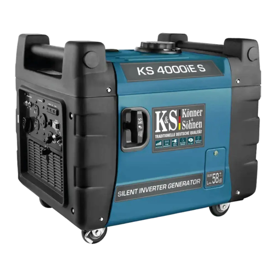
Page 16: Ks 4000Ie S, Ks 4000Ieg S-Profii
9. OVERVIEW AND COMPONENTS OF INVERTER GENERATORS KS 4000iE S, KS 4000iEG S-Profi Fig. 12 1. Carrying handles 4. Manual starter 2. Fuel tank cap 5. Casters 3. Oil level cap 6. Control panel KS 4000iE S CONTROL PANEL Fig. 13 1. - Page 17 KS 4000iEG S-Profi CONTROL PANEL Fig.14 1. 2x16А AC outlets 6. 12V/8A DC outlet 2. Display 7. Ground terminal 3. Start switch 8. Fuel valve 4. Economy mode switch 9. Generator parallel socket 5. 12V DC fuse...
-
Page 18: Overview And Components Of Inverter Generator
10. OVERVIEW AND COMPONENTS OF INVERTER GENERATOR KS 7100iE G-Profi Fig. 15 1. Gas connection 5. Manual starter 2. Fuel tank cap 6. Casters 3. Control panel 7. Fuel valve 4. Carrying handle 8. Air choke KS 7100iE G-Profi CONTROL PANEL Fig. -
Page 19: Overview And Components Of Inverter Generator
11. OVERVIEW AND COMPONENTS OF INVERTER GENERATOR KS 7200iEG S-Profi Fig. 17 1. Fuel tank cap 4. Support leg 2. Carrying handle 5. Casters 3. Service cover 6. Damper KS 7200iEG S-Profi CONTROL PANEL Fig. 18 1. 230V AC fuses 6. - Page 20 12. INVERTER GENERATOR SPECIFICATIONS Model KS 1200i KS 2100i Voltage, V Maximum power, kW Nominal power, kW Power factor, cos φ Current, A (max.) 5.22 7.83 Frequency, Hz Outlets 1х16А (230V) 2х16А (230V) Engine start Manual Manual Fuel tank volume, L...
- Page 21 ТSPECIFICATIONS OF INVERTER GENERATORS IN SOUNDPROOF HOUSING Model KS 2000i S KS 3300i S KS 3300iEG S-Profi Voltage, V Maximum power, kW Nominal power, kW Power factor, cos φ Current, A (max.) 8.70 14.35 14.35 Frequency, Hz Outlets 2х16А (230 V) 2х16А (230 V) 2х16А...
-
Page 22: Generator Specifications
INVERTER GENERATOR SPECIFICATIONS Model KS 3500i KS 3500iE G-Profi KS 7100iE G-Profi Voltage, V Maximum power, kW 7.0* Nominal power, kW 6.3* Power factor, cos φ Current, A (max.) 14.35 15.22 30.43 Frequency, Hz 1х16А (230 V) Outlets 1х16А (230 V) 1х16А... - Page 23 SPECIFICATIONS OF INVERTER GENERATORS IN SOUNDPROOF HOUSING Model KS 4000iE S KS 4000iEG S-Profi KS 7200iEG S-Profi Voltage, V Maximum power, kW 7.0* Nominal power, kW 6.3* Power factor, cos φ Current, A (max.) 17.39 17.39 30.43 Frequency, Hz 1х16А (230 V) Outlets 2х16А...
-
Page 24: Functional Description Of Inverter Generators
13. FUNCTIONAL DESCRIPTION OF INVERTER GENERATORS PARALLEL FUNCTION The total output power of the generators can be increased by connecting two inverter generators together using the Parallel Unit. Parallel connection of two identical generator models ensures double nominal output power of these models. When connecting generators of different capacities using the Parallel function, the output power is two times the nominal power of the generator with lesser capacity. - Page 25 “ON” MODE Fig. 20 When the ECON switch is in the “ON” position, the control unit monitors the engine speed, reducing it commensurate with the connected load. If the engine speed is not enough to generate electricity to provide the load, the control unit will automatically increase the engine speed.
- Page 26 PLEASE NOTE! It is advisable to enable the TURBO mode only after warming up the generator for 1-2 minutes. Do not abuse the TURBO mode! This may adversely affect the engine operation. LСD DISPLAY Generator models KS 3300i S, KS 3500i, KS 4000iE S, KS 3300iEG S-Profi, KS 3500iE G-Profi, KS 4000iEG S-Profi, KS 7100iE G-Profi, KS 7200iEG S-Profi have control panel equipped with a LСD display.
-
Page 27: Terms Of Use Of Inverter Generator
14. TERMS OF USE OF INVERTER GENERATOR It is recommended to ground the generator before operating it for the first time. Before starting the device, remember that the total power of the connected power consumers should not exceed the nominal power of the generator. TYPES OF POWER CONSUMERS AND START-UP CURRENT There are two types of power consumers (electrical devices connected to the generator): active and reactive. - Page 28 PLEASE NOTE! Useful tip: If the engine stalls or does not start, turn the engine switch to the “ON” position, and then pull the manual starter. If the oil level indicator flickers for several seconds, add oil and restart the engine. ISS-Systems With more than 10 years of experience, TM Könner &...
-
Page 29: Check Before Getting Started
AC INDICATOR When the generator is running and producing electricity, the AC indicator light is on. DC FUSE The DC protector automatically switches to “OFF” when the current of the operating electrical device is higher than the rated current. To use this equipment again, turn on the DC fuse again by pressing the “ON”... -
Page 30: Getting Started
CHECKING THE OIL LEVEL The generator is transported free of motor oil. Do not start the engine until it is filled with sufficient amount of motor oil. HILL TO 1. Unscrew the oil dipstick and wipe it out with a clean cloth. 2. - Page 31 COMMISSIONING In the first 20 operating hours of the generator, the following requirements should be met: 1. During commissioning, do not connect power consumers, the power of which exceeds 50% of the nominal (operating) power of the device. 2. After commissioning, be sure to change the oil. It is better to drain oil while the engine is still hot after operation to ensure quick and complete oil draining.
- Page 32 WARNING - DANGER! Do not connect two or more devices at a time. The start-up of many devices requires high power. Devices should be connected one at a time according to their power rating. Do not connect any power consumers within the first 2 minutes after the generator has been started.
- Page 33 DISCONNECT ALL DEVICES BEFORE STOPPING THE GENERATOR! Do not stop the generator if it has any devices connected to it. This may disable the generator or devices connected to it! PLEASE NOTE! Use care when the generator is running! You can use the generator if the voltmeter indicates a value of 230V ±10% (50 Нz).
- Page 34 CHARGING AN EXTERNAL 12 V BATTERY Plug the battery into the generator’s 12V outlet. Turn on the engine, then connect the generator to the battery to charge. Before you start charging the battery, make sure that the 12V DC fuse is turned on. 1.
-
Page 35: Maintenance
18. MAINTENANCE Maintenance work listed in section “Maintenance” should be performed on a regular basis. If you cannot perform maintenance work on your own, please contact the authorized service center to request the required maintenance work. PLEASE NOTE! The manufacturer shall not be liable for any damage caused by failure to perform maintenance work. - Page 36 REPLACING OR ADDING MOTOR OIL Fig. 25 If the oil level drops, fresh oil must be added to ensure proper operation of the generator. Check the oil level according to the maintenance Upper level schedule. WARNING - DANGER! To avoid burns, handle the oil carefully because it is still very hot even after stopping the engine.
-
Page 37: Recommended Maintenance Schedule
20. RECOMMENDED MAINTENANCE SCHEDULE Unit Action Level check Motor oil Replacement Cleaning Air filter Replacement Cleaning Spark plug Replacement Level check Fuel tank Cleaning Fuel Cleaning filter - If the generator often operates at high temperature or high load, the oil should be replaced every 25 operating hours. -
Page 38: Air Filter Maintenance
21. AIR FILTER MAINTENANCE Air filter should be checked for contamination from time to time. Regular maintenance of the air filter is necessary to maintain sufficient air flow in the carburetor and reduce fuel consumption. Air filter Fig. 28 CLEANING THE FILTER: 1. -
Page 39: Damper And Flame Arrester Maintenance
Fig. 29 Spark plug 0.60 - 0.80 mm Electrodes 23. DAMPER AND FLAME ARRESTER MAINTENANCE The engine and damper will get very hot after the generator has been started. Do not touch the engine or damper with any part of your body or clothing during inspection or repair until they have cooled down. -
Page 40: Fuel Filter
24. FUEL FILTER Fig. 32 PLEASE NOTE! Never use gasoline while smoking or in the immediate vicinity of an open flame. 1. Remove the fuel tank cap and fuel filter. 2. Clean the filter with gasoline. 3. Wipe the filter and replace it. 4. -
Page 41: Troubleshooting
28. TROUBLESHOOTING Fault Probable cause Remedy Engine switch set to OFF Set the engine switch to ON Fuel tank is empty Add fuel Engine contains dirty or old fuel Replace fuel in the engine Engine will not start Low oil level Add fresh oil to the specified level Fuel tank is dirty... -
Page 42: Average Power Ratings Of Devices
29. AVERAGE POWER CONSUMPTION OF DEVICES Device Power (W) Iron 500-1100 Hair dryer 450-1200 Coffee machine 800-1500 Electric cooker 800-1800 Toaster 600-1500 Heater 1000-2000 Vacuum cleaner 400-1000 Radio 50-250 Grill 1200-2300 Baking oven 1000-2000 Fridge 100-150 TV set 100-400 Perforator 600-1400 Drill 400-800... -
Page 43: Warranty Terms
30. WARRANTY PROVISIONS Inverter generators are covered by a one-year warranty from the date of purchase, which is confirmed by record and seal of the seller in the warranty card. All faults caused by the manufacturer during the warranty period will be eliminated free of charge. - Page 45 NOTES ________________________________________________ ________________________________________________ ________________________________________________ ________________________________________________ ________________________________________________ ________________________________________________ ________________________________________________ ________________________________________________ ________________________________________________ ________________________________________________ ________________________________________________ ________________________________________________ ________________________________________________ ________________________________________________ ________________________________________________ ________________________________________________ ________________________________________________ ________________________________________________ ________________________________________________ ________________________________________________ ________________________________________________ ________________________________________________ ________________________________________________ ________________________________________________ ________________________________________________ ________________________________________________ ________________________________________________ ________________________________________________ ________________________________________________ ________________________________________________ ________________________________________________ ________________________________________________ ________________________________________________ ________________________________________________ ________________________________________________ ________________________________________________ The current list of service centers can be found on the official importer’s website: www.ks-power.de/en...
- Page 46 KONTAKTDATEN Deutschland: DIMAX International GmbH Deutschland, Hauptstr. 134, 51143 Köln, www.ks-power.de info@dimaxgroup.de...
Need help?
Do you have a question about the KS 4000iE S and is the answer not in the manual?
Questions and answers