Table of Contents
Advertisement
Advertisement
Table of Contents

Related Manuals for K&S KS 3000

Summary of Contents for K&S KS 3000
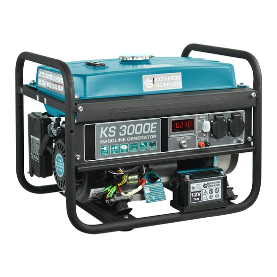
- Page 1 Instruction Please, read this manual before use! Gasoline generator KS 3000 KS 10000E 1/3 KS 3000E KS 10000E KS 7000 KS 10000E-3 KS 7000E KS 10000E ATS KS 7000E-3 KS 10000E-3 ATS KS 7000E ATS KS 7000E-3 ATS KS 7000E 1/3...
-
Page 2: Table Of Contents
CONTENTS 1. INTRODUCTION 2. SAFETY INFORMATION 2.1. Working area 2.2. Electrical safety 2.3. Personal safety 2.4. Precautions when working with gasoline generator 2.5. Precautions when working with hybrid generator 3. SAFETY SYMBOLS DECRYPTION 3.1. Symbols description when working with generator 3.2. -
Page 3: Introduction
1. INTRODUCTION We are grateful to you for your purchase of ТМ Könner & Söhnen series gasoline powered generator. This manual contains safe working recommendations, operation and adjustment description of these generators and maintenance instructions. Manufacturer reserves the right to make alterations into the generators, which may not be reflected in this manual. -
Page 4: Electrical Safety
- Please set the generator on a flat hard horizontal surface. To reduce vibration during operation and to avoid damage to the surface, where the generator is installed, it is equipped with dampers. - Please don’t use the generator near flammable gases, liquids or dust. When using the generator exhaust system gets very hot. -
Page 5: Precautions When Working With Gasoline Generator
ATTENTION - DANGER! Non compliance to these requirements may result in generator combustion or explosion, as well as in electric wiring ignition inside the structure. - To avoid inhaling exhaust gas, the generator does not have to work in conditions of poor ventilation. -
Page 6: Safety Symbols Decryption
3. SAFETY SYMBOLS DECRYPTION 3.1. SYMBOLS DESCRIPTION WHEN WORKING WITH GENERATOR pic 1 pic 2 a. Be careful when using the device! Follow e. The device generates electricity. Follow safety rules listed in manual. safety precautions to avoid electric shock. b. -
Page 7: Description Of Generator Inscription
4. DESCRIPTION OF GENERATOR INSCRIPTION EXCEPT SAFETY SYMBOLS GENERATOR CONTAINS FOLLOWING INSCRIPTION: Specification table. For different models this table is different. All charachtetistics are given in the «Specifications». Indicates the noise level. For different models this indicator is different. All charachtetistics are given in the «Specifications». Note which direction you should open air dampers. -
Page 8: Main Overview
5. MAIN OVERVIEW pic 4 1. Fuel tank cap 7. Fuel valve 2. Control panel 8. Air filter 3. 12 V power battery 9. Air flap switch (electric start models only) 10. Fuel level indicator 4. Oil-depth gage 11. Silencer 5. -
Page 9: Dual Fuel Generator Overview
6. DUAL FUEL GENERATOR OVERVIEW Except the nodes, described in gasoline generator main overview (pic 5) dual fuel generators are additionally equipped with LPG supply hose. That allows the generator to work either on gasoline or on LPG. pic 5 LPG supply hose reductor... -
Page 10: Models Description
8. MODELS DESCRIPTION KS 3000 KS 3000 E KS 3000 G Model Voltage, V Max Power, kW Nominal Power, kW Frequency, Hz 13,04 13,04 13,04 Current max, A 2*16А 2*16А 2*16А Outlets Fuel Tank Volume, l 50% power working time... - Page 11 KS 7000 KS 7000E KS 7000E G Model Voltage, V Max Power, kW Nominal Power, kW Frequency, Hz 23,91 23,91 23,91 Current max, A 1*16А 1*16А 1*16А Outlets 1*32A 1*32A 1*32A Fuel Tank Volume, l 50% power working time voltage voltage voltage LED display...
- Page 12 KS 7000E-3 KS 7000E ATS Model KS 7000E-3 ATS 230-400 230-400 Voltage, V Max Power, kW Nominal Power, kW Frequency, Hz 9,93 23,91 9,93 Current*, A 1*16А 1*16А 1*16А Outlets 1*16A (3p) 1*32A 1*16A (3p) Fuel Tank Volume, l 50% power working time LED display voltage voltage...
- Page 13 Model KS 10000E KS 10000E-3 KS 10000E ATS KS 10000E-3 ATS 230-400 230-400 Voltage, V Max Power, kW Nominal Power, kW Frequency, Hz 34,78 14,45 34,78 14,45 Current max, A 1*16А 1*16А 1*16А 1*16А Outlets 1*32A 1*16A (3p) 1*32A 1*16A (3p) Fuel Tank Volume, l 50% power working time voltage...
- Page 14 Model KS 7000E 1/3 KS 10000E 1/3 Voltage, V Max Power, kW Nominal Power, kW Frequency, Hz 23,91 9,93 34,78 14,45 Current max, A 1*16A (400V), 1*16A (400V) Outlets 1*32A (230V) 1*32A (230V) Fuel Tank Volume, l 50% power working time voltage, frequency, voltage, frequency, LED display...
-
Page 15: Control Panel Types
9. CONTROL PANEL TYPES 9.1. GENERATOR PANEL pic 6 1. LED display 2. Emergency circuit breaker 3. Sockets 4. Start/electrostart 5. Direct current sockets 12 V 6. Grounding 9.2. GENERATOR PANEL FOR MODELS: KS 7000E ATS, KS 7000E-3 ATS, KS 10000E ATS, KS 10000E-3 ATS pic 7 1. -
Page 16: Digital Display Of Gasoline Generators
9.4. DIGITAL DISPLAY OF GASOLINE GENERATORS The choice of indicators occurs by pressing a button on the display, selection of indicators is cyclic. In this mode, the display shows the voltage, in volts. In this mode, the display shows the current frequency, in hertz. -
Page 17: Before Starting
11. BEFORE STARTING 11.1. CHECK THE FUEL LEVEL 1. Please wear protective gloves to avoid getting gasoline on the skin. 2. Remove the fuel tank cap and check the fuel level 3. Add fuel to the filter level if necessary 4. -
Page 18: Gasoline Generator Engine Start
12.1. GASOLINE GENERATOR ENGINE START 1. Fuel supply valve to be set in “OPEN” position. 2. Air shutter to be set to “CLOSED” position. 3. Upon manual start – set the engine switch to “ON” position. 4. Start slowly pulling the starter till you feel slight resistance. By an abrupt movement pull the starter to full cord length. -
Page 19: Generator Launch In Ats Mode (For Generators With Ats)
pic 11 pic 12 launch button release flap hose pic 13 1. Position the air flaps when running on gasoline. 2. Position the air flaps when running on gas. 3. Operating mode. IMPORTANT! Place the container with gas only vertically, according to the instruction manual for gas cylinders. -
Page 20: Generator Connection
13. CONNECTION OF GENERATOR WITH BUILT-IN ATS Connection of the generator with the built-in ATS to the consumers of electricity and the central power supply. 13.1. SCHEME OF CONNECTION OF A SINGLE-PHASE GENERATOR Power supply Consumers of electricity L- Line Electrical counter N - Neutral 13.2. -
Page 21: Stopping The Engine
DURING GENERATOR OPERATION: • You may use the generator, if the voltage meter displays the value 230\/ + / - 10% (50Ng). • Watch the voltage meter and in case of excessive indices values, stop the generator operation. • Connection to continuous voltage socket is used for accumulator recharge only. Upon accumulator unit recharge, it is mandatory to verify the polarity correctness ( + to +, - to - ). -
Page 22: Maintenance Schedule
Such damages are also: • Damages occurred as a result of using non original spare parts; • Corrosion damages and other results of improper equipment storage; • Damages occures as a result of maintanance performance by inexperienced and unauthorized specialists. This manual compliance. -
Page 23: Recommended Oils
2. Place a drain oil holding tank under the engine. 3. Turn the drain cap, located in the engine under the oil-depth gage cap, by means of a hexagon spanner 10 mm for all verifications of KS 3000. 4. Wait till the oil drains. -
Page 24: Air Filter Technical Maintenance
18. AIR FILTER TECHNICAL MAINTENANCE It is necessary to, from time to time, check the air filter and clean any contaminations. Regular air filter maintenance is necessary to maintain sufficient carburetor air inflow. Cleaning the filter: 1. Open the clips on the upper cap of the air filter. 2. -
Page 25: Battery Use
pic 16 pic 17 Spark 0,60 - 0,80 mm plug Electrode 20. BATTERY USE The generator battery is not subject to service. If the generator is not used for a long time, the battery may fail. To prolong battery life it is recommended to do battery charging with an external device (not included) every three months. -
Page 26: Generator Transportation
22. GENERATOR TRANSPORTATION For easy generator transportation use packaging, which generator was sold in. Secure the box with the generator to avoid tipping ir on the side of the carriage. Before moving the generator drain the fuel and disconnect the terminals of the battery. To move the generator from one place to another lift it by holding the frame. -
Page 27: Average Power Usage
24. AVERAGE POWER USAGE Device Average power usage Air hair dryer 450-1200 Iron 500-1100 Electric cooking stove 800-1800 Toaster 600-1500 Coffee machine 800-1500 Air heater 1000-2000 BBQ Grill electric device 1200-2300 Vacuum cleaner 400-1000 Radio 50-250 TV set 100-400 Refrigerator 100-150 Oven 1000-2000... -
Page 28: Warranty Service Terms
25.WARRANTY SERVICE TERMS TERMS AND CONDITIONS: The international manufacturer warranty is 1 year. The warranty period starts from the date of purchase. In cases when warranty period is longer than 1 year according to local legislation please contact your local dealer. The Seller which sells the product is responsible for granting the warranty. Please contact the Seller for warranty. - Page 30 CONTACTS Germany ks-power.de info@dimaxgroup.de Poland ks-power.pl info.pl@dimaxgroup.de Ukraine ks-power.com.ua sales@ks-power.com.ua...
Need help?
Do you have a question about the KS 3000 and is the answer not in the manual?
Questions and answers