Table of Contents
Advertisement
Quick Links
Advertisement
Table of Contents
Troubleshooting

Related Manuals for THORLABS TQD001


Summary of Contents for THORLABS TQD001
- Page 1 TQD001 Quad Detector User Guide Original Instructions...
-
Page 2: Table Of Contents
Contents Chapter 1 Safety .................... 4 1.1 Safety Information .................. 4 1.2 General Warnings .................. 4 Chapter 2 Overview and Setup ..............5 2.1 Introduction ..................... 5 2.2 T-Cube Controller Hub ................6 2.3 APT PC Software Overview ..............7 2.3.1 Introduction ...................... -
Page 3: Introduction 3
Appendix B PID Tutorial ................62 Appendix C Preventive Maintenance ............63 Appendix D Specifications and Associated Parts ........64 Appendix E APTQuad Control Method Summary ........65 Appendix F Regulatory ................67 Appendix G Thorlabs Worldwide Contacts ..........71... -
Page 4: Chapter 1 Safety
Chapter 1 Safety 1.1 Safety Information For the continuing safety of the operators of this equipment, and the protection of the equipment itself, the operator should take note of the Warnings, Cautions and Notes throughout this handbook and, where visible, on the product itself. The following safety symbols may be used throughout the handbook and on the equipment itself. -
Page 5: Chapter 2 Overview And Setup
Chapter 2 Overview and Setup 2.1 Introduction The TQD001 quadrant detector T-Cube is designed to work with the Thorlabs PDP and PDQ series detector heads. As a member of the T-Cube family of controllers this unit benefits from a unified ActiveX software interface, USB connectivity, very compact footprint and compatibility with the T-Cube Hub System. -
Page 6: T-Cube Controller Hub
Important Note For convenience and consistency, all system descriptions and examples throughout this manual assume that the TQD001 is used with a pair of TPZ001 T-Cube Piezo Controllers. It is also possible to use the MDT693 or BPC202 controllers, or a 3rd party piezo amplifier, or even a non-piezo actuated positioning element, as long as they have suitable low voltage external control inputs and a manual adjustment facility. -
Page 7: Apt Pc Software Overview
2.3 APT PC Software Overview 2.3.1 Introduction As a member of the APT range of controllers, the TQD001 Quadrant Detector shares many of the associated software benefits. This includes USB connectivity (allowing multiple units to be used together on a single PC), fully featured Graphical User Interface (GUI) panels, and extensive software function libraries for custom application development. -
Page 8: Aptuser Utility
Chapter 2 2.3.2 APTUser Utility The APTUser application allows the user to interact with a number of APT hardware control units connected to the host PC. This program displays multiple graphical instrument panels to allow multiple APT units to be controlled simultaneously. All basic operating parameters can be altered and, similarly, all operations (such as switching between Monitor, Open Loop and Closed Loo modes) can be initiated. -
Page 9: Apt Config Utility
T-Cube Quad Detector Reader 2.3.3 APT Config Utility There are many system parameters and configuration settings associated with the operation of the APT Server. Most can be directly accessed using the various graphical panels, however there are several system wide settings that can only be made 'off-line' before running the APT software. -
Page 10: Apt Server (Activex Controls)
With the APT system, ActiveX Controls are deployed to allow direct control over (and also reflect the status of) the range of electronic controller units, including the TQD001 Quad Detector. Software applications that use ActiveX Controls are often referred to as 'client applications'. -
Page 11: Software Upgrades
APT controllers. 2.3.5 Software Upgrades Thorlabs operate a policy of continuous product development and may issue software upgrades as necessary. Detailed instructions on installing upgrades are included on the APT Software... -
Page 12: Chapter 3 Initial Installation
If you experience any problems when installing software, contact Thorlabs on +44 (0)1353 654440 and ask for Technical Support. DO NOT CONNECT THE CONTROLLER TO YOUR PC YET 1) Insert the CD into your PC. -
Page 13: Mechanical Installation
T-Cube Quad Detector Reader 4) Once you are familiar with the installation procedure, click the ‘Install APT Software’ hyperlink displayed on the Welcome dialogue screen. 5) Follow the on-screen instructions - see the Installation Guide supplied for more information 3.2 Mechanical Installation 3.2.1 Environmental Conditions Warning Operation outside the following environmental limits may adversely affect... -
Page 14: Removing The Baseplate
Chapter 3 3.2.3 Removing the Baseplate The baseplate must be removed before the rubber feet (supplied) can be fitted, or the unit is connected to the USB controller hub. Detail A Detail B Baseplate attachment screws Baseplate removed and rubber feet fitted Fig. -
Page 15: Electrical Installation
This signal is proportional to the total amount of light hitting the detector. Note Thorlabs supply a variety of SMA to BNC and SMC to BNC adaptor and extension cables. Please see our catalog, or visit www.thorlabs.com for further details. -
Page 16: Supply Voltage And Current Requirements
DC power supply of the rating detailed in Section 3.3.2. 2) Switch on the Power Supply unit. Thorlabs offers a compact, two-way power supply unit (TPS002), allowing up to two Quad Detector or Piezo driver T-Cubes to be powered from a single mains outlet. -
Page 17: Using The Usb Controller Hub
Piezo Cubes (firmware version 2.0.X). The firmware version is displayed on power up. A clash can occur if a TSG001 Strain Gauge Cube and a TQD001 Quad Detector Cube are combined on the hub, and both attempt to drive voltage signals out via the Hub. In this instance it is recommended that... -
Page 18: Chapter 4 Getting Started - Basic Operation
Throughout this section, the sensor described is a PDQ80A quad detector. However, the TQD001 unit is also compatible with other Thorlabs detectors, such as the PDQ30C IR detector head or the PDP90A Lateral Effect Detector. -
Page 19: Detector Head Descriptions
PDQ80A or PDQ30C sensor type is selected, the display shows the XDiff and YDiff values that the sensor outputs in Volts. The TQD001 always reads the voltages, but additionally for the PDP90A sensor, it is capable of calculating the exact X, Y position from these voltages. -
Page 20: Pdq80A And Pdq30C Quadrant Detector Heads
The two difference signals are voltage analogs of the light intensity difference sensed by the pairs of photodiode elements in the array. These three signals are sent in analog form to the TQD001 Quad Detector via its rear panel DETECTOR IN (6-pin HRS) connector. -
Page 21: Use Of The Sum And Difference Signals For Alignment
Second, the beam position is adjusted until the X-Axis (XDIFF) and Y-Axis (YDIFF) difference signals are at minimum. This procedure results in the beam being centered on the quad photodiode array. See Section 4.5.3. for a description of how this procedure is implemented using the TQD001 Quad Detector cube. -
Page 22: Beam Size Considerations
Chapter 4 4.2.4 Beam Size Considerations The light spot applied to the sensor must be smaller than the diameter of the sensor photodiode array, and the recommended beam diameters are as follows: PDQ80A - 1 to 3.9 mm, PDP90A - 0.2 to 7 mm, PDQ30C - <0.5 mm. A decrease in output signal strength is observed as the light spot crosses the separation boundary of the sesnor arrays, usually referred to as ‘the gap’. -
Page 23: Control Panel Buttons And Indicators
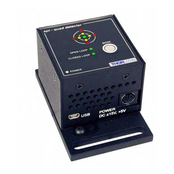
T-Cube Quad Detector Reader 4.3 Control Panel Buttons and Indicators apt - quad detector Target OPEN LOOP CLOSED LOOP MODE POWER Fig. 4.5 Panel Controls and Indicators MODE Button - selects between Monitor, Open Loop and Closed Loop modes - see Section 4.4. -
Page 24: Operating Modes
Chapter 4 4.4 Operating Modes The MODE button on the top panel, is used to toggle between Monitor, Open Loop and Closed Loop modes. When operating in 'Monitor' mode (top panel OPEN and CLOSED LOOP LEDs not lit), the X axis (XDIFF) and Y axis (YDIFF) difference signals from the detector, are fed through to the rear panel SMA connectors for use in a monitoring application - see Fig. - Page 25 T-Cube Quad Detector Reader PDQ80A Quad Detector XDIFF LV OUT XDIFF YDIFF LV OUT YDIFF OPEN LOOP MODE: The XDIFF and YDIFF signals are routed to the DSP. The DSP either sets the outputs to zero, or holds them at their last closed loop voltage (dependent on the setting of the 'Position Demand In Open Loop Mode' parameter in the Settings panel).
- Page 26 Chapter 4 Fig. 4.8 Single Axis PID Control Schematic Diagram HA0185T Rev 9 Feb 2014...
-
Page 27: Basic Application Example
4.5 Basic Application Example 4.5.1 Introduction It is likely that the TQD001 Quad Detector will be used as a closed loop controller in a potentially complicated opto-mechanical system. This section illustrates its deployment in a beam stabilization application, and describes the main steps required to build a working closed loop system. -
Page 28: Basic Operation
Chapter 4 Caution During item (6) ensure the power supply unit is isolated from the mains before connecting to the T-Cube units. Always power up the units by connecting their power supply to the mains. DO NOT connect the T-Cube units to a 'live' external power supply. - Page 29 T-Cube Quad Detector Reader the demand sense is positive - see Fig. 4.10. If they move to the right, the demand sense is negative. Note The default settings for the Position Demand Sense is ‘Positive’, which is correct for the set up shown in Fig. 4.9. If the check described at item (5) shows a negative demand sense, then it will be necessary to connect a PC to change the Position Demand Sense parameter in the Settings panel - see Section 6.2.
-
Page 30: Signs Of Instability
Chapter 4 8) Press the MODE button on the Quad Detector to select ‘Closed Loop’ mode, i.e. the CLOSED LOOP LED is lit. The Quad Detector unit now takes over the alignment, and controls the piezo units to drive the piezo mirror to direct the laser beam to the central position. The beam position within the sensor array is indicated by the target display on the top panel. -
Page 31: Using The Target Display
T-Cube Quad Detector Reader 4.5.6 Using the Target Display The ‘target’ display shows the horizontal and vertical position of the laser beam within the quadrant detector sensor array. When used in conjunction with the display on the piezo cubes, it can also be used to show when the piezo actuators are near the ends of their travel and need re-centering. - Page 32 Chapter 4 2) Adjust the OUTPUT pot on the piezo drivers until both displays read 37.5 V. 3) Adjust the manual actuators on the turning mirror as necessary to position the laser beam in the detector array. 4) Press the MODE button on the Quad Detector to select ‘Closed Loop’ mode. 5) The piezos drivers will position the piezo mirror such that the laser beam is held central within the detector array, i.e.
-
Page 33: Chapter 5 Pc Operation - Tutorial
Chapter 5 PC Operation - Tutorial 5.1 Introduction Note Familiarize yourself with operation and set up of the basic system detailed in Chapter 4 before attempting operation from the GUI panel. The following brief tutorial guides the user through a typical series of actions and parameter adjustments performed using the GUI panel displayed by the APTUser utility. -
Page 34: Building An Auto-Alignment System - Pc Operation
Note There are only enough hub lines to facilitate comms between one TQD001 unit and a pair of TPZ001 units. If a second TQD001 unit is used with 2 TPZ001 units, then SMA to SMA connections are required. If no hub is available, then the SMA cables are required, regardless of what revision number piezo cubes are used. -
Page 35: Wiring And Software Settings For Revision 1 Piezo Drivers
5.2.2 Wiring and Software Settings for Revision 1 Piezo Drivers The following procedure describes a typical set up, with the TQD001 Quad Detector being used with a pair of Rev 1 TPZ001 piezo driver cubes - see Fig. 5.2 for a general system schematic diagram. - Page 36 Wait while Windows installs the drivers for the new hardware. 10) Run the APTUser utility Start/All Programs/Thorlabs/APT/APT User. 11) Click the ‘Settings’ button on GUI panel of one of the Piezo Drivers. The Settings panel is displayed - see Fig. 5.3. Note To identify the piezo unit associated with a GUI panel, click the ‘Ident’...
- Page 37 T-Cube Quad Detector Reader 12) Make the following parameter settings, as shown in Fig. 5.3 Drive Input Source - Select Pot (+ SW). Loop Mode - Select Open Loop Output Voltage Range - For the ASM003 mirror shown in Fig. 5.2, set 75V, (for other piezo mirrors, set 75V, 100V or 150V whichever is applicable)..
-
Page 38: Using Revision 1 Piezo Drivers On The Tch002 Hub
Chapter 5 21) It is advisable to click the ‘Persist Settings To Hardware’ box. These settings will then be loaded on each power up cycle. Fig. 5.4 Quad Detector Settings 22) Click ‘OK to save the settings. 5.2.3 Using Revision 1 Piezo Drivers On The TCH002 Hub The internal communication lines of the TCH002 hub cannot be used with Revision 1 T-Cube units. -
Page 39: Wiring And Software Settings For Revision 2 Piezo Drivers - Hub Operation
USB comms connections to all controller cubes. The following procedure describes a typical set up, with the TQD001 Quad Detector cube being used with a pair of Rev 2 TPZ001 piezo driver cubes on the TCH002 controller hub - see Fig. - Page 40 - see the Getting Started guide for more information. 10) Run the APTUser utility Start/All Programs/Thorlabs/APT/APT User. 11) Click the ‘Settings’ button on GUI of the Piezo Driver fitted in bay 1. The Settings panel is displayed.
- Page 41 T-Cube Quad Detector Reader 13) It is advisable to click the ‘Persist Settings To Hardware’ box. These settings will then be loaded on each power up cycle. Fig. 5.6 Piezo Driver Settings - Rev 2 Hardware 14) Click ‘OK to save the settings. 15) On the GUI panel, turn the ‘Output’...
- Page 42 Chapter 5 20) Set the LV Signal Routing parameter to SMA + Hub, as shown in Fig. 5.7.. Fig. 5.7 TQD001 Settings Panel - Hub Operation 21) Set the X & Y Feedback Sense to Positive. 22) Set the X & Y Feedback Gain to 1.0.
-
Page 43: Revision 2 Piezo Driver Hub Mounting Options
T-Cube Quad Detector Reader 5.2.5 Revision 2 Piezo Driver Hub Mounting Options When the T-Cube Quad Detector and two piezo drivers are used together on the hub, signals can be routed via dedicated internal communication channels. These channels are selected via the GUI Settings panel. If Channel 2 is selected, the feedback signals run between adjacent pairs of T-Cube bays (i.e. - Page 44 Chapter 5 bay 3 bay 1 TPZ001 TPZ001 Hub Channel 2 Hub Channel 1 ✓ V OLT S V OLT S C ONT R OL C ONT R OL OPEN LOOP J OG J OG CLOSED LOOP MODE POWER P OWE R P OWE R bay 3 TPZ001...
-
Page 45: Basic Operation
X-axis piezo actuator. Turn the control knob on the piezo GUI to increase the piezo drive voltage. The spot in the main display of the TQD001 GUI should move along the X axis with very little Y axis movement. If the beam moves in the Y-axis, or diagonally, the piezo controller is connected to the wrong actuator. - Page 46 Chapter 5 Fig. 5.11 X-axis Position Demand Sense Check 6) Check that the piezo controller connected to the LV OUT YDIFF connector, is driving the Y-axis piezo actuator. Turn the control knob on the piezo controller to increase the piezo drive voltage. The laser beam should move along the Y axis with very little X axis movement.
- Page 47 T-Cube Quad Detector Reader Using the GUI Displays The small left hand display shows the detector XDiff, YDiff and Sum signal values in Volts. Also shown are the XOut and YOutvalues, which are applicable in ‘closed loop mode only. These values show the low voltage position demand signals applied to the piezos in order to keep the beam central in the detector.
- Page 48 Chapter 5 When the unit is switched to closed loop mode, the spot moves towards the center of the display as the piezo units drive the piezo mirror to reposition the laser beam. Fig. 5.13 Repositioning the Laser Beam But the X Out and Y Out values are nearly ‘10’, which means that the piezos are near the limit of their travel.
- Page 49 T-Cube Quad Detector Reader 14) The piezos drivers will position the piezo mirror such that the laser beam is held central within the detector array, i.e. for a 75V piezo, the X Out and Y Out values show around 0V (37.5V piezo drive) and the spot is central within the display as shown below.
-
Page 50: Signs Of Instability
Chapter 5 5.2.8 Signs Of Instability The Control loop PID settings allow the system response to be tuned to a particular application. Higher proportional and integral coefficients decrease the residual error in the system and also allow the system to respond more quickly to a disturbance (i.e. the system is able to dampen vibrations at a higher frequency range). -
Page 51: Creating A Simulated Configuration Using Apt Config
To create a simulated configuration proceed as follows: 1) Run the APT Config utility - Start/All Programs/Thorlabs/APT/APT Config. 2) Click the 'Simulator Configuration' tab. Fig. 5.15 APT Configuration Utility - Simulator Configuration Tab... - Page 52 4) In the 'Simulator' field, check the ‘Enable Simulator Mode’ box. The name of the most recently used configuration file is displayed in the 'Current Configuration' window. 5) In the ‘Control Unit’ field, select ‘Quad Controller (TQD001)’. HA0185T Rev 9 Feb 2014...
-
Page 53: Programmed Operation
8 digits (as displayed in the ‘Load Configuration Details’ window), the first two digits are added automatically and identify the type of control unit. The prefixed digits relating to the TQD001 T-Cube Quad Detector are: 89xxxxxx - T-Cube Quad Controller 7) Click the 'Add' button. -
Page 54: Chapter 6 Software Reference
Fig. 6.1 Quad Detector Software GUI Note The serial number of the TQD001 Quad Detector associated with the GUI panel, the APT server version number, and the version number (in brackets) of the embedded software running on the unit, are displayed in the top right hand corner. - Page 55 T-Cube Quad Detector Reader X,Y Display Mode - The detector head provides top-minus-bottom (Y-Axis alignment) and left-minus-right (X-Axis alignment) difference signals, together with a signal that is the sum of signals (total beam power) from all four sensors of the internal photodiode array.
- Page 56 Chapter 6 Operating Mode - These three buttons are used to toggle between Monitor, Open Loop and Closed Loop modes. The LED in the button is lit when a particular mode is selected - see Section 4.4. for more details. When operating in 'Monitor' mode, the X axis (XDIFF) and Y axis (YDIFF) difference signals from the detector, are fed through to the rear panel SMA connectors for use in a monitoring application.
-
Page 57: Settings Window
T-Cube Quad Detector Reader 6.2 Settings Window When the 'Settings' button on the GUI panel is clicked, the 'Settings' panel is displayed. This panel allows data such as PID parameter values to be entered or set. The various parameters are described below. Fig. - Page 58 Chapter 6 Differential - This parameter damps the rate of change of the output, thereby decreasing the overshoot which may be caused by the integral term. However, the differential term also slows down system response. If set too high, it could lead to instability due to signal noise amplification.
- Page 59 T-Cube Quad Detector Reader LV OUT/XDIFF and LV OUT/YDIFF connectors, which are then used by the piezo T- cubes to drive the piezo mirror in order to keep the beam central in the detector. (See the next topic for a typical application. Under normal operating conditions, these values are between -10 V and +10 V however, some applications may require the limits to be less than this.
-
Page 60: Appendix A Connector Pinout Details
Connector Pinout Details A.1 Power Connector Thorlabs recommends that the Quad Detector cube is operated with Thorlabs power supply TPS002, as it was specifically designed for use with this product. However, to enable customers to use the cube in installations where a ±15V and 5V power is already available, the piezo cube can be operated with a different external power supply, such as a bench or lab supply. - Page 61 T-Cube Quad Detector Reader A.2 DETECTOR IN Connector The DETECTOR IN connector on the rear panel is a HIROSE HR10A-7R-6S connector, which mates with the connector on the sensor cable. Fig. A.2 shows the pin configuration as viewed by looking at the rear panel of the cube..
-
Page 62: Appendix Bpid Tutorial
Appendix B PID Tutorial The TQD001 implements a PID control loop for closed loop control. A PID (Proportional-Integral-Derivative) controller is a widely used feedback mechanism that is relatively easy to tune. The reason why tuning is required in most cases is because individual setups can be very different. -
Page 63: Appendix C Preventive Maintenance
The equipment contains no user serviceable parts. There is a risk of electrical shock if the equipment is operated with the covers removed. Only personnel authorized by Thorlabs Ltd. and trained in the maintenance of this equipment should remove its covers or attempt any repairs or adjustments. -
Page 64: Appendix D Specifications And Associated Parts
Appendix D Specifications and Associated Parts D.1 Specifications Parameter Value X & Y Diff Outputs Female SMA -10 V to >10 V Sum Output Female SMA 0 to >10 V X & Y Position Demand Outputs SMA 0 to >10 V Closed Loop X &... -
Page 65: Appendix E Aptquad Control Method Summary
Appendix E APTQuad Control Method Summary The ActiveX functionality for the Quad Detector Reader T-Cube is accessed via the APTQuad Control Object, and provides the functionality required for a client application to control a number of T-Cube Quad Detector Reader units. To specify the particular controller being addressed, every unit is factory programmed with a unique 8-digit serial number. - Page 66 Appendix E LLSetGetDigOPs Sets or Gets the user digital output bits encoded in 32 bit integer. LoadParamSet Loads stored settings for specific controller. ReadPositionDemands Returns the present values for the XPos and YPos position demand signals (-10 V to +10V) ReadSumDiffSignals Reads the present values for the SUM, XDIFF and YDIFF signals...
-
Page 67: Appendix F Regulatory
Appendix F Regulatory F.1 Declarations Of Conformity F.1.1 For Customers in Europe This equipment has been tested and found to comply with the EC Directives 89/336/EEC ‘EMC Directive’ and 73/23/EEC ‘Low Voltage Directive’ as amended by 93/68/EEC. Compliance was demonstrated by conformance to the following specifications which have been listed in the Official Journal of the European Communities: Safety EN61010: 2001 Installation Category II, Polution Degree II. - Page 68 • left over parts of units disassembled by the user (PCB's, housings etc.). If you wish to return a unit for waste recovery, please contact Thorlabs or your nearest dealer for further information. HA0185T Rev 9 Feb 2014...
- Page 69 T-Cube Quad Detector Reader F.2.2 Waste treatment on your own responsibility If you do not return an "end of life" unit to the company, you must hand it to a company specialized in waste recovery. Do not dispose of the unit in a litter bin or at a public waste disposal site.
- Page 70 Appendix F 6.3 CE Certificate HA0185T Rev 9 Feb 2014...
-
Page 71: Appendix G Thorlabs Worldwide Contacts
Appendix G Thorlabs Worldwide Contacts For technical support or sales inquiries, please visit us at www.thorlabs.com/contact for our most up-to-date contact information. USA, Canada, and South America UK and Ireland Thorlabs, Inc. Thorlabs Ltd. sales@thorlabs.com sales.uk@thorlabs.com techsupport@thorlabs.com techsupport.uk@thorlabs.com Europe Scandinavia... - Page 72 www.thorlabs.com...
Need help?
Do you have a question about the TQD001 and is the answer not in the manual?
Questions and answers