Advertisement
QUICK REFERENCE GUIDE
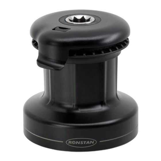
O R B I T
W I N C H
™
20
ST
RA6201 Single Speed, Self-tailing Winch
DETERMINE WINCH MOUNTING POSITION
Position the winch in the desired location. Ensure the surface is flat and the
line entry angle is acceptable (3-8º as shown below).
!
Incorrect line entry
Mounting surface not flat
Ensure the Drive gear is aligned to the line entry as per the orientation on
the template.
ROPE ENTRY
RA6201 MOUNT TEMPLATE
SCALE 1:1
FASTENERS: 5 x M6 (1/4")
THIS DRAWING /LIBRARY HAS BEEN PRODUCED FOR USE IN DECK PLANS ONLY; SOME DETAILS HAVE BEEN OMITTED.
SHOULD ACCURATE DIMENSIONS BE REQUIRED SUCH AS HOLE SPACING, LENGTHS, ETC.
PLEASE CONTACT RONSTAN FOR FURTHER INFORMATION.
Output Drive
Line Entry
Download the drilling template and complete Product Manual for this winch from ronstan.com/orbitwinch for detailed instructions regarding installation, operation, service and maintenance.
Download the complete Product Manual for
this winch from ronstan.com/orbitwinch for
detailed instructions regarding installation,
operation, service and maintenance.
INSTALLATION
3-8°
STEP 1
Clean the mounting surface and tape the drilling template in position so that it
matches the desired winch mounting position and orientation.
STEP 4
With the template in place, drill the Ø6.5mm holes for the M6 mounting bolts (or
9/32" holes for 1/4" bolts).
Remove the template, clean away any debris from the holes, and clean the deck
thoroughly to ensure deck sealant can adhere properly.
RA6201 Specifications
Power ratio:
1st speed:
18:1
Line dia.:
6-10mm (1/4" - 3/8")
Weight:
1.7 kg (3.7 lb)
MWL:
550 kg (1210 lb)
1
2
3
STEP 2
Pull back the spring-loaded release latch on the self-tailing arm with a fingertip (1), then
rotate the arm slightly in an anti-clockwise direction (2) until it can be lifted clear of the
winch (3).
STEP 5
Apply sealant under the base of the centre stem around the mounting holes, ensuring
that the drainage channels remain clean and free of sealant. For mounting on metal
surfaces, the base must also be completely isolated from the mounting surface to
prevent galvanic corrosion. Isolation is also recommended for installation on raw
carbon fibre surfaces.
996124—Rev.1
STEP 3
Pull upward on the drum to remove it from the centre stem. Place the centre stem on
the template with mounting hole positions aligned, to check that orientation of rope
entry in relation to Output Drive Gear is correct.
STEP 6
Fit the winch to the deck using large washers (or backing plate) and locking nuts
below deck. Apply Tef-Gel™ under the head of each mounting fastener to isolate it
from the aluminium centre stem. To avoid wearing the anodised surface of the stem,
use a hex key to prevent the fastener from turning and use a spanner to tighten the nuts
from below.*
* 5x M6 or 1/4" Grade 316 stainless steel fasteners. Use of A4-70 DIN912 hex socket cylinder head
screws is recommended, installed at a torque setting of no more than 7.1Nm as per industry
standards.
Tef-Gel™ is a trademark of Ultra Safety Systems, Inc.
Advertisement
Table of Contents

Related Manuals for Ronstan ORBIT WINCH 20ST


Summary of Contents for Ronstan ORBIT WINCH 20ST
- Page 1 7.1Nm as per industry standards. Tef-Gel™ is a trademark of Ultra Safety Systems, Inc. Download the drilling template and complete Product Manual for this winch from ronstan.com/orbitwinch for detailed instructions regarding installation, operation, service and maintenance.
- Page 2 Turn off power to an electric winch before performing any maintenance or service tasks. Failure to do so could result in significant damage and/or serious injury. Download the complete Product Manual for this winch from ronstan.com/orbitwinch for detailed instructions regarding installation, operation, service and maintenance.
Need help?
Do you have a question about the ORBIT WINCH 20ST and is the answer not in the manual?
Questions and answers