GARO Entity Pro Installation And Operation Manual
Hide thumbs
Also See for Entity Pro:
- Installation (2 pages) ,
- Installation and operations (91 pages) ,
- Installation (2 pages)

Related Manuals for GARO Entity Pro


Summary of Contents for GARO Entity Pro
- Page 1 GAROEntityProinstallationand operation GARO Entity Pro installation and operation Version 1.3...
-
Page 2: Table Of Contents
CONTENTS 1 Introduction....................5 1.1 Document description............... 5 1.2 Product description................5 1.2.1 Feature description ..............5 1.2.2 Definitions ................5 1.3 Intended use..................6 1.4 Contact .................... 6 2 Safety......................9 2.1 Safety definitions................9 2.2 Safety instructions for installation ............. 9 3 Product overview .................. - Page 3 4.13.3 To install the load interface in an electrical cabinet ... 50 4.14 GARO Connect................56 4.14.1 The GARO Connect app ........... 56 4.14.2 GARO Connect app process overview......57 4.14.3 GARO Connect app symbols overview ......58 4.14.4 Owner................61 4.14.5 Installer................68 5 Operation ....................85 5.1 To charge an electrical vehicle ............
-
Page 5: Introduction
OCPP based charging stations in the (s) with an RFID tag or an app. The EV driver can use the same systems. Entity Pro is a wallbox that is easy to use, GARO Connect app to monitor charging of an EV. -
Page 6: Intended Use
The organization shares the same owner(s) and it is possible to create groups of EV drivers to manage access to the charging stations. GARO Electric Ireland Ltd Owner: An owner is a person who owns one or several 19/307 Northwest Business Park, Blanchardstown, IE- charging stations. - Page 7 Introduction GARO Electric Ltd Sales & Customer Service Unit 16 Urban Express Park Aston Hall Road Birmingham, B6 7FH Version: 1.3...
-
Page 9: Safety
If a defect is found, speak to the owner of the blinking a slowly in red (0,5 Hz). charging station. The owner can be found in the GARO Connect app. Only use charging cables with no visible defects and intended for charging the relevant EV. -
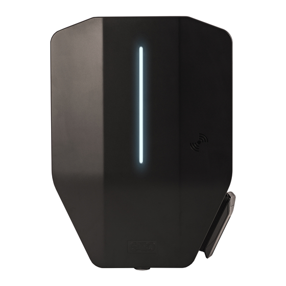
Page 11: Product Overview
E. Protection cover. The protection cover is an accessory that is used for a prepared installation without an attached charging unit. Garo offers various installation accessories. Both as a complete charging station or as individual system components. Version: 1.3... -
Page 12: Charging Station Packaging Overview
Product overview 3.2 CHARGING STATION PACKAGING OVERVIEW Charging Station (CS) Charging Unit (CU) Front cover Installation bracket - single (IB) Installation bracket - double (IB) Charging station (CS) A charging station is a complete kit, packed in a box. It contains all parts required for EV charging. -
Page 13: Product Variants
Product overview 3.3 PRODUCT VARIANTS The Entity Pro charging station (and separate charging unit) is available in several product variants. Version: 1.3... - Page 14 • With or without phase balancing. • With or without mobile communication modem (Cat-M1/NB/GPRS). • With or without ISO 15118 HW support. • With or without SIM, supplied from GARO. • With or without PME protection (UK only). Version: 1.3...
-
Page 15: Charging Station Overview
Product overview 3.4 CHARGING STATION OVERVIEW A. Power connection terminal (in and out). H. All-pole circuit breaker, manual reset. B. Bracket terminal connector. I. PE disconnection relay (PME protection variant only) (for UK only). C. Charging unit connector. J. 2 port Ethernet switch RJ45. D. -
Page 16: Dimensions
Product overview N. Type 2 outlet. O. Front cover lock. P. Indication light. Q. Optional ID-label placement after installation. R. Label, load interface type. S. Sealing label. T. RFID reader area. 480 mm 3.5 DIMENSIONS 150 mm Dimensions for bracket hole positions: 340 mm Ø6 240 mm... -
Page 17: Double Version Installation Bracket (Ib)
Product overview Ø6 Ø6 Ø6 Ø6 Ø6 Ø6 Ø6 Ø6 Ø6 Bracket and knockout dimensions: Bracket and knockout dimensions: Ø32 Ø32 Knockout Knockout Ø32 Ø32 Knockout Knockout Ø32 Ø32 Ø32 Ø32 Ø32 Ø32 Knockout Knockout Knockout Knockout Knockout Knockout 3.5.2 DOUBLE VERSION INSTALLATION BRACKET (IB) Bracket and hole dimensions: Version: 1.3... -
Page 19: Installation
Comply with local requirements. • Only a technically skilled person with the necessary knowledge of the GARO Entity charging station may replace the charging unit. 4.3 PERSONAL PROTECTIVE EQUIPMENT WARNING Make sure that the correct personal protective equipment for the installation is available. -
Page 20: To Do A Plan For The Installation
NOTE H. Make sure that the necessary tools and testing instruments for installation are available. RFID tags are available as accessories at GARO. I. Make sure that the correct installation material is D. Plan the power supply and current availability available. -
Page 21: To Generate The Installation Code
Installation K. Use the GARO Connect app to generate the NOTE installation code. The owner normally provides There can only be one installation code for each the installation code to the installer. However, location. However, an installation code can be used by... -
Page 22: To Ensure The Necessary Installation Material
Installation 4.8 TO ENSURE THE NECESSARY INSTALLATION MATERIAL • Make sure that the necessary installation materials are available. A. Power cable. B. Ethernet cable with suitable RJ45 plug, if ethernet is used. C. Screws and plugs that are suitable for the wall material, at a maximum diameter of 6 mm and a maximum screw head diameter of 14 mm. -
Page 23: To Decide Internet Connection Type
Installation 4.9 TO DECIDE INTERNET CONNECTION TYPE 4.10 TO CONNECT SEVERAL CHARGING STATIONS • Decide what internet connection should be used for the installation and what unit that should be used for NOTE the role of communication master. There are 3 types Several charging stations can be connected as one of internet connection that is possible to use for cable multidrop/daisy chaining. -
Page 24: Simple Setup Scenarios
The external IT-network is built up of switches, preferably forming star-connected networks. However, the built-in 2-port switch of the Entity PRO charging station and Entity Balance Advance, can be used to build a long chain of installation. A disadvantage is that a service break in one unit disturbes the units that follow. - Page 25 Installation New units that are a part of a DLM system must be This method is only used for adding a load interface added (connected) to groups. There are 4 main ways to acting as DLM master 1 level up. Use this when a do this: existing group requires a dynamic DLM, that is a DLM master that monitors/measures current in a...
-
Page 26: To Decide The Position Of The Charging Station
(C) perspective. Comply with local requirements. 4.12 CABLE INSTALLATION The GARO Entity is designed to work with both 400 V TN-S (default) and 230 V IT/TT. PE L1 If a 230 V IT system is to be used, the marking of the installation bracket should be updated, using the supplied marking stickers. -
Page 27: To Install The Stickers For It 230 V
Installation As alternative, a separate PEN terminal block with 3 terminals, to be used for with "creation" of a neutral conductor, can be used. 4.12.1 TO INSTALL THE STICKERS FOR IT 230 V NOTE This instruction is only valid for IT 230 V systems. 1. -
Page 28: To Install The Installation Bracket To A Wall
Installation 4.12.3 TO INSTALL THE INSTALLATION BRACKET b. If there are several charging stations to be daisy- TO A WALL chained with the same feeding cable, also remove the knock-out for the outlet hole of the 1. Decide the position of the charging station. Refer to second power cable. -
Page 29: To Prepare The Power Cable For Installation
Installation NOTE Ground stands and polemont fixtures are available as accessories. The workflow is similar. See separate manuals for those accessories. 8-14 mm max. 5 mm 4.12.4 TO PREPARE THE POWER CABLE FOR INSTALLATION CAUTION If it is necessary to pass the connection terminal with connection of the power cable due to dual power cables in the same direction, route the wires on the opposite side from the connection terminal, compared to where... - Page 30 Installation 2 mm ~ 500 mm 2. Thread the power cable through the grommet in the 4. Install the cable strain relief to fixate the power power cable inlet hole. cable. 12 - 17 mm TX20 15 - 20 mm 18 - 24 mm NOTE 3.
-
Page 31: To Connect The Power Cable To The Terminal
Installation 6. Cut and dismantle the wires. Use a wire ferrule (A) in the GARO Connect app to reflect exactly how each for strained power wire conductors (B). charging station is connected to the grid. Another reason to install charging stations with rotation... - Page 32 Installation a. TN system. b. TN-C. PE L1 PE L1 PE L1 PE L1 Version: 1.3...
-
Page 33: To Install A Second Power Cable (Daisy-Chaining Method)
Installation c. IT system. 3. To remove any wire, push a TX20 screwdriver on the terminal and pull the wire out. TX20 2. Install the wires to the terminal block. a. If the wires have strained conductors (A), use a TX20 screwdriver and push the orange button to 4.12.6 TO INSTALL A SECOND POWER CABLE open the terminal. -
Page 34: To Prepare The Installation Bracket With A Second Ethernet Cable
Installation 4. Put a piece of tape on the cable to increase the cable diameter and to tighten/seal the hole. 5. Install the ethernet cable to a RJ45 plug. T568A T568B 1 2 3 4 5 6 7 8 1 2 3 4 5 6 7 8 NOTE The recommended length for the ethernet cable inside the installation bracket is 400 mm. -
Page 35: To Connect The Charging Station To The Internet With Communication Modem (Cat-M1/Nb/Gprs)
2. Install the SIM card to the dedicated slot in the external, insulated/potential-free contact. The control charging station. logic is configured in the GARO Connect app. By default, charging is disabled if the contact is closed. The control logic can be toggled: Closed contact = limitation, or Open contact = limitation. -
Page 36: To Change The Position Of The Type 2 Outlet Or Fixed Cable
Installation 3. Dismantle the control cable and the wires inside the control cable. OPEN Max 1.5 mm² 10 mm NOTE If wires need to be disconnected, use a flat screwdriver NOTE to push the orange button to open the terminal. The recommended conductor strip length is 10 mm. -
Page 37: To Do A Test Of The Power Connection
Installation 4.12.12 TO DO A TEST OF THE POWER CONNECTION WARNING Electrical power can cause serious personal injury or death. 1. Make sure that the power/voltage off by an appropriate insulating main switch. I ON I ON I ON I ON 2. - Page 38 4. Switch the power/voltage to on. 7. Read the QR code on the installation bracket using the GARO Connect App. At this step, it is time to connect the charging station, created in the GARO Connect App to the physical installation bracket.
-
Page 39: To Install A Protection Cover
Installation 4.12.14 TO ATTACH THE CHARGING UNIT TO THE CAUTION INSTALLATION BRACKET If the charging station is set up without any internet connectivity, it will allow charging at maximum current 1. If applicable, install the ethernet cable(s) in the defined by the attached charging unit. The default ethernet ports on the charging unit. - Page 40 Installation 3. Attach the charging unit to the installation bracket. Press equally on the charging unit with both hands. CAUTION Make sure that no cables get pinched and that the charging unit can meet the edges of the installation bracket. 5.
-
Page 41: To Do A Final Functionality Test Of The Product
If the charging station needs manual internet settings, that is if it shall act as a master with a local Wi-Fi as the internet connection, make the internet connectivity settings in the GARO Connect app. Refer to To prepare the installation (installer), page 68 4.12.15 TO DO A FINAL FUNCTIONALITY TEST OF... - Page 42 Installation seconds. Make sure that the all-pole circuit breaker is triggered. < 90 5. Set the charging station to state B (shown with a blue solid light indication). 9. Reset the all-pole circuit breaker. 10. Do a test of the earth faults (AC and DC) with a test instrument.
-
Page 43: To Mount The Front Cover Of The Charging Unit
3. After the final testing, the installation of the charging station can be declared ready in the GARO Connect app, The charging station becomes available to use and visible to EV drivers with 2. Lock the front cover at the bottom of the charging access rights. - Page 44 Installation should preferably be the connection point for internet, calculated as the sum of all charging station currents, or but this is not a requirement. Any unit of the group can several charging stations together with other loads. If be defined as internet gateway/communication master. the connection group consists of other loads as well, The connection group is also defined by a maximum then the real current needs to be monitored, using a...
- Page 45 Mesh network. DLM Algorithm: The load interface is necessary in most installations and all settings are done in the GARO Connect app. The If the total current consumption exceeds the set limit, communication platform is in the same network as the then the current consumption is limited to within the charging station(s).
-
Page 46: Load Interface Installation Overview
Installation 4.13.2 LOAD INTERFACE INSTALLATION OVERVIEW GARO Entity Balance Basic Functional grounding of CT's CT3+ (White) K CT3-/GND(Black) L CT2+ (White) K CT2-/GND(Black) L CT1+ (White) K CT1-/GND (Black) L CT1-3: 0-333 mV output Wi-Fi antenna Indication light Ethernet HAN(RJ12) - Page 47 Installation GARO Entity Balance Advanced Functional grounding of CT's CT3+ CT3- CT2+ CT2- CT1+ CT1- CT1-3: 0-5 A output Wi-Fi antenna Indication light Ethernet Ethernet Connect to charging station, Connect to charging station, other load interface other load interface or network switch.
- Page 48 Installation 100A LI 1 LI 2 Version: 1.3...
- Page 49 Installation GARO Connect 3-level Connection group (CG) Communication structure example CLOUD MODEM w. SIM CARD INTERNET LOCAL LI 1 Wi-Fi Internet Gateway (CG A1) ROUTER MASTER CG A1 LI 2 Wi-Fi Wi-Fi Mesh Mesh Ethernet cable Ethernet cable Ethernet Ethernet cable...
-
Page 50: To Install The Load Interface In An Electrical Cabinet
GARO Entity Balance basic and GARO Entity Balance advanced. NOTE This chapter shows the installation of the GARO Entity Balance BASIC model. The process for the GARO Entity Balance ADVANCED is similar. If the group contains local production (like PV/solar panels) with a net output power that can get close to the max. - Page 51 Installation Max 1,5 mm² 8 mm 2-pole 2-10 A 4. Install the load interface unit (C) on the DIN rail. 6. Connect the load interface to the protection device. NOTE Functional Ground connection (here shown as PE) is only recommended to use when connecting current transformers.
- Page 52 CT1-/GND (Black) L transformers of 2 output types can be used. 0-333 mV or 0 – 5 A output range. For easy installation, GARO recommends the 0-333 mV type when possible. 0–333 mV is only valid for GARO Entity Balance basic 8 mm and 0–5 A is only valid for GARO Entity Balance...
- Page 53 (K) and negative (L) cable of the measured current. current transformer (CT) clamp. GRID 11. The GARO Entity Balance BASIC is prepared for HAN communications to the modern main utility CT3+ (White) K meters, based on RJ12 or RJ45 connections. HAN is only available on GARO Entity Balance basic.
- Page 54 Current transformers on their own cannot provide that information. 13. The load Interface is a part of the total GARO Entity charging station communication network, that could be based on either ethernet cable, Wi-Fi mesh or a Wi-Fi that is part of an existing IT infrastructure.
- Page 55 O OFF O OFF refer to 7.1 Troubleshooting, page 19. Download the GARO Connect app on AppStore or Google Play store. 10:06 18. The light indicator on the front panel turns red at power/voltage up. Make sure that the indicator light on the load interface turns green.
-
Page 56: Garo Connect
GARO Connect app. The GARO Connect app can be downloaded from Google Play or App store on a digital device. Register as a new user in the GARO Connect app. Use an e-mail address as usename. GARO Connect 21. -
Page 57: Garo Connect App Process Overview
Installation 4.14.2 GARO CONNECT APP PROCESS OVERVIEW The GARO Connect app is based on a standard/ station, and the installer of the charging station. The startup process for both the owner of the charging illustration shows the process from both perspectives. -
Page 58: Garo Connect App Symbols Overview
Installation 14. Owner: Manage access control for EV drivers, monitor the system, refer to To prepare the installation (owner), page 4.14.3 GARO CONNECT APP SYMBOLS OVERVIEW Icon Icon name Icon information Location Click the icon to access the list of available locations. - Page 59 Installation No internet The icon informs that there is no internet. The master charging station must have internet access via modem, Wi-Fi, or an ethernet. Internet connection active via Wi-Fi The icon informs that a radio based internet connection link is active and working. The icon also informs that the internet connection is available direct (to the internet connectivity master) or indirect to a non-master unit through a...
- Page 60 The icon is for the charging cable Type 2 that is connected to the charging station. This means that the charging station has a fixed cable. Only possible for GARO Entity CS. Type 2 outlet The icon is for the Type 2 outlet, which can be used to charge the EV.
-
Page 61: Owner
2. Create an organization if it is needed. This is not These instructions are for the owner. To see the whole mandatory for every installation. Add more persons process overview of the GARO Connect app, refer to as owners. 4.14.2 GARO Connect app process overview, page 3. - Page 62 Installation 2. Create a new account in the GARO Connect app. Follow the instructions on the screen. 3. Log on to the GARO Connect app with provided credentials. 4. Select Manage Locations . Version: 1.3...
- Page 63 Installation 5. Choose location. 6. Select Invite Installer . NOTE It is recommended to change name on the default location. Preferably, the name should specify the physical place of the unit, including address and coordinates. In this example, the location is called Main office.
- Page 64 7. Generate an installation code. An e-mail can be • generated to the installer through the GARO Charger settings Connect app. This is not mandatory, any The settings for each charging station can be communication channel is fine.
- Page 65 Installation • • Enable charging station Charging station access Under Manage charging stations > Charging Each charging station can be set to free use Settings , each charging station can be enabled/ (default). This enables access for everybody. If the disabled by the owner.
- Page 66 It is possible to create charger NOTE groups at a later time. If the EV driver does not have a GARO Connect account, an invitation email will be sent to that EV driver. •...
- Page 67 Installation organization, which means they can be used in The owner is normally given default access to use several locations within an organization. the charging stations of the location. The organization is a good tool when administrating several locations. • Advanced owner tools Additional owners can be added and removed to a location and organization.
-
Page 68: Installer
If a new installation code is generated by the owner, the 11. Declare the installation as complete in the GARO old one is invalid, like a key. Connect app and hand over the installation to the The installation process of the installer is described in owner. - Page 69 Installation 2. Log on to the GARO Connect app with provided credentials. If it is the first time logging in, edit personal settings. 3. Choose Installers menu . Version: 1.3...
- Page 70 Installation 4. Select either New installation for new location or 5. Change installation for existing location : Select a Change installation for existing location . location. 6. Enter the installation code provided by the owner. Version: 1.3...
- Page 71 Installation 7. New installation for new location : Create a new installation for a new location. During the installation, which starts with the creation of the location, the installer acts as a temporary owner. After the installation, the location is transferred to the actual owner.
- Page 72 Installation 3. Enter a device name and select Garo Entity for 4. Once the unit is added, connect the unit to a group. charging stations or Garo Entity Balance for load Click the unit to connect it to a group.
- Page 73 Installation NOTE All units, even a single charging station, must be tied to a group. The workflow of adding units must follow the connectivity and the DLM structural paths. Always start with the unit that will act as the internet gateway followed by the closest units of the different levels.
- Page 74 Installation NOTE To make a DLM work, all units in the DLM must be part of a structured communication group. In small installations, only 1 internet gateway/communication master is required. 5. Enter a group name and set the maximum current (Ampere) for the group.
- Page 75 To set the internet connection settings for the first unit, the internet gateway, a direct connection must be set up between the device (mobile with the GARO Connect app) and the charging station. c. Attach the charging unit and turn the power/ voltage on.
- Page 76 Connect NOTE It is also possible to enter the Wi-Fi credentials as plain text in the GARO Connect app, if the QR code can not be used. b. Wait until the box lights up with a solid green light. This can take up to 5 minutes.
- Page 77 Installation c. Select how to connect to the internet: d. The internet media icon will turn green once connected to the internet. - ethernet cable to router e. Close the connection between the mobile device - local Wi-Fi connection to existing Wi-Fi with and the charging station.
- Page 78 Installation 9. Software update. There are several configuration settings that are possible to adjust with the GARO Connect app. In Software can always be updated, but never the GARO Connect app, information is available as downgraded as this is not allowed due to cyber support for each available setting.
- Page 79 DLM group If additional units are installed into a DLM system, each unit must be defined into a group structure. The GARO Connect app tool controls the workflow order, adding one unit at a time following the closest relationships.
- Page 80 Installation The example below show how to add the ungrouped load interface main fuse unit into the DLM home group structure. The DLM home group unit has already been created for unit CS 1. 2. To add a unit to an existing group, select a group and click Next .
- Page 81 DLM and connection group masters. NOTE The group is not fully created until the ID is set. 5. Click Next to continue the installation. Complete the remaining installation steps and declare the installation finished in the GARO Connect app. Version: 1.3...
- Page 82 Installation 6. The unit is added to the selected group. 7. View the hierarchy of the DLM groups and Internet groups under Connection groups . Version: 1.3...
- Page 83 However, the internet connection should be automatic if an ethernet cable or a mesh Wi-Fi is used. If a Wi-Fi connection is used, follow the instructions in the GARO Connect app. Transfer location If the installation is performed on behalf of the owner, transfer the location back to the owner.
- Page 84 Installation NOTE If the owner is not a user of the GARO Connect app, an invitation will be sent out via email. Version: 1.3...
-
Page 85: Operation
NOTE It is possible to lock the charging cable to a Type 2 outlet using the Garo Connect app. It is only the EV driver that has locked the charging cable and the owner of the charging station that can unlock the charging cable. -
Page 86: Indication Light
Operation 5.1.1 INDICATION LIGHT 100% When Meaning Green solid light. The charging station is available for charging. Green slow blinking light, 1 Hz. The charging station waits for either a connection to or a disconnection of an EV. Yellow solid light. The Type 2 contact is not in correct position. -
Page 87: To Schedule Charging
The charging station has no power or the intensity of the indication light is reduced. 5.2 TO SCHEDULE CHARGING c. Use the GARO Connect app and log in as the EV driver that started the charging. 1. Open the GARO Connect app on a mobile device. - Page 88 Operation CAUTION Do not leave the Type 2 contact on the ground. Always hang it up or store it in a dry location. Version: 1.3...
-
Page 89: Maintenance
5. Wait for the device to restart and the light to turn electric power and disable the charging station in the green. GARO Connect app. Contact an authorized service center. 6.4 TO DO AN EARTH FAULT TEST 6.3 TO DO A FACTORY RESET NOTE Do an earth fault test 2 times/year. -
Page 90: To Do A Reset After A Minor Ground Fault
If it is configured, a notification is sent to the owner and the EV driver that uses the charging station, in the GARO Connect app. The circuit breaker can trip either due to an earth fault, short circuit or overload. -
Page 91: To Replace A Charging Unit
1. Turn the power/voltage off. NOTE Only 1 installation bracket can be installed, connected to 1 charging station in the GARO Connect app. If an installation bracket is to be reused in another location, it must first be deleted from the first location. -
Page 92: Pme - Protective Multiple Eathing (Uk Versions Only)
Action when triggered: (A red, slow blinking (0.5 Hz) indication on the charging station LED, an error message can be read in the GARO Connect app). A notification is sent to the user and the owner if configured. 1. Disconnect the EV. -
Page 93: Troubleshooting
Contact the installer or GARO support. The charging station (CS) is deactivated by the owner using the Garo Connect app or a Pro charging station is deactivated by an external enable signal. Example: A The indication light shows a fixed red light. - Page 94 Troubleshooting Let the owner do a check of the power and current status in the GARO Connect app. The signalled current, that is The charging power is too low. what the charging station allows the EV to use, can be reduced due to load balance and thermal derating.
-
Page 95: Technical Data
Technical data 8 TECHNICAL DATA 8.1 CHARGING STATION TECHNICAL DATA Product type GARO Entity Pro Standards IEC 61851-1 IEC 62955 IEC 61439-7 EN 60898-1 EN 61008-1 EMC classification 2014/30/EU Installation method Wall in a single and/or double installation bracket. (Stand and pole mount fixtures are available as... - Page 96 Technical data Weight 3-3.7 kg without cable (depending on product variant) Cable length (fixed cable version) 4.5 m/5 m/8 m NOTE IEC 61851-1 allows max. 7.5 m. Size single version charging station, height*width*depth 340*240*150 mm Size double version charging station, 340*495*145 mm height*width*depth Residual current limit...
-
Page 97: Load Interface Technical Data
Technical data Power connection terminals 2.5–16 mm , spring type Warranty 2 years Design product life cycle 10 years installation/30 000 hours charging at 20 C Appliance class. Protection against electric shock Class I equipment with PE connection 8.2 LOAD INTERFACE TECHNICAL DATA Standards EN 62368-1 EMC Classification... -
Page 98: Accessories
Relay output 12-230 V, 1 A Implemented energy meters modbus Implemented enerymeters M-bus Garo GNM3D-RS485 Garo GNM3D-Mbus Garo GNM3D-LP RS485 Garo GNM3D-LP Mbus Garo GMI3D-LP RS485 Carlo Gavazzi EM210 with Rogowski 8.3 ACCESSORIES For available accessories, refer to the GARO website at www.garo.com. Version: 1.3... -
Page 99: Source Code
GPL-2.0, and GPL-3.0 and other open source licenses. A copy of the licenses are available in a separate document. Source code can be obtained from GARO for a period of 3 years after the final shipment of the product, which may be no earlier than 2025–01–01 for a fee. -
Page 101: Eu Declaration Of Conformity
EU Declaration of conformity EU DECLARATION OF CONFORMITY Version: 1.3... - Page 102 EU Declaration of conformity Version: 1.3...
Need help?
Do you have a question about the Entity Pro and is the answer not in the manual?
Questions and answers