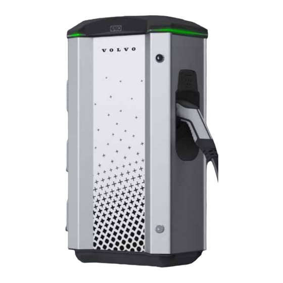
Summary of Contents for GARO LS4 MINI
- Page 1 LS4 MINI Assembly instructions / End User Instructions (EN) GARO AB Box 203, SE–335 25 Gnosjö Phone: +46 (0) 370 33 28 00 info@garo.se garo.se...
-
Page 2: Table Of Contents
TABLE OF CONTENT About this manual INFORMATION Warnings Cautions Notes Content INSTALLATION USER MANUAL Normal use LED indications Dimensional sketch Technical specifications Service / Maintenance Service and maintenance form Installation Form... -
Page 3: About This Manual
INFORMATION LS4 MINI is designed exclusively for charging electric GARO LS4 MINI is an EVSE station for Mode-3 AC charging up vehicles. to 43kW. LS4 MINI must be grounded according to local country Below are some example of standard features: installation requirements. -
Page 4: Cautions
Incorrect installation and testing of the LS4 MINI could potentially damage either the vehicle and/or the LS4 MINI itself. Poor quality electricity may harm the LS4 MINI and or the vehicle. An example of such source of poor quality electricity may be private power generators. -
Page 5: Installation
(figure 1) 3. Mount the LS4 MINI on a wall or on a pedestal, figure 1-6. 6 Ø 8,5mm (screws not included) Note: Wall installation requires a minimum 20mm distance between the wall and the LS4 MINI to ensure correct cooling, (figure 4) Recommendation is to use the included wallbracket. - Page 6 INSTALLATION L1, L2, L3, N 6Nm L1, L2, L3, N 2,5-16mm² 5Nm, 2,5-10mm² 5Nm, 25-50mm² 10Nm 4x ALU-CU adapters 16-50mm² 10Nm 2,5-10mm² 5Nm 16-50mm² 10Nm (figure 3) (figure 4) 0,8Nm +-0,05 (figure 5) Pedestal = Accessory...
-
Page 7: User Manual
USER MANUAL USER MANUAL Normal use Connect the charging cable to the EV (Electric Vehicle). If authorization is activated, please hold a valid RFID-tag against the RFID reader on the side of the LS4 you want to use or use the operator app to authorize charging. - Page 8 USER MANUAL LED light indication When Cause of error When RFID is presented Charging station is verifying the RFID in backend cloud service. Blinking yellow The upstream circuit breaker have been triggered. Charging station and internal 4-pole main circuit breaker inside the bottom of charging station meters are powerless.
- Page 9 USER MANUAL LED light indication Measure 1 Measure 2 If the orange "alarm" LED indicator on the charge controller is firm lit, then the charge controller needs to be replaced. Reset the RCCB inside the charging station. Verify that the 8-pole quick connection on the charge controller is properly connected.
- Page 10 USER MANUAL LED light indication Measure 1 Measure 2 Reset circuit breaker in upstream switchboard. Check mainbreaker, reset it if it is deactivated. Check mainbreaker (1-pole 10A), reset it if it is deactivated. Verify that 12V power supply unit is receiving 220V AC power via terminals L &...
-
Page 11: Dimensional Sketch
USER MANUAL LED light indication Indication / fault code in Web UI OCPP fault code IDLE (available) - (A) Vehicle not connected IDLE (available) - (B) Vehicle connected not ready Firm green IDLE (available) - (C) Vehicle connected ready IDLE (available) - (A) Vehicle not connected Blinking green (3 blinks) AUTHORIZED (available) - (A) Vehicle not connected... -
Page 12: Technical Specifications
USER MANUAL Technical specifications Product type LS4 MINI Standards / Directives IEC 61851-1 and IEC 61439-7 EMC Classification: 2014/30/EU Installation method: Wall / Ground* Installation environment: Indoor / Outdoor Location type: Non-restricted Access Rated Voltage: 230V / 400V 50Hz Installation systems:... -
Page 13: Service / Maintenance
You can normally find information inside the LS4 MINI if it is connected to a supervised system. -
Page 14: Installation Form
USER MANUAL Installation Form LS4 MINI Model: M nr: ELECTRICAL INSTALLATION DATA Group fuse (A): Supply cable dimension: FUNCTION TEST Testbox: Date: Sign Installer: Company Name: Owner/Customer Name: Installation address:... - Page 15 GARO AB Box 203, SE–335 25 Gnosjö Phone: +46 (0) 370 33 28 00 info@garo.se garo.se...


Need help?
Do you have a question about the LS4 MINI and is the answer not in the manual?
Questions and answers