
Related Manuals for National Instruments PXIe-7856R


Summary of Contents for National Instruments PXIe-7856R
- Page 1 (217) 352-9330 | Click HERE Find the National Instruments PXIe-7856 / PXIe-7856R at our website:...
-
Page 2: Hardware Overview
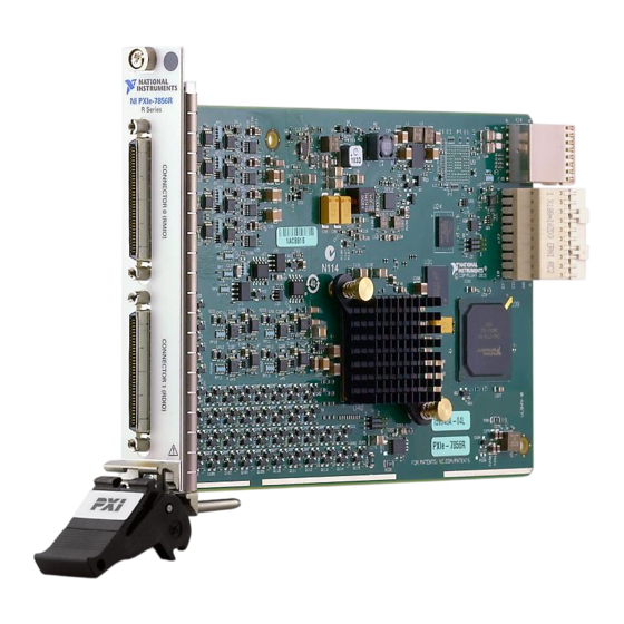
8 AI, 8 AO, 48 DIO, 1 MS/s AI, Kintex-7 160T FPGA This document provides compliance, pinout, connectivity, mounting, and power information for the NI PXIe-7856R. Hardware Overview The following high-level block diagram represents the NI PXIe-7856R. Figure 1. NI PXIe-7856R Block Diagram 100 MHz Flash... - Page 3 Ground reference for the analog input signal Analog output signal connection AOGND Ground reference for the analog output signal 2 | ni.com | NI PXIe-7856R User Manual Artisan Technology Group - Quality Instrumentation ... Guaranteed | (888) 88-SOURCE | www.artisantg.com...
-
Page 4: Connectivity Options
The provided clock source must be stable and glitch-free. Ground connection Supply (+5 Vout) 5 V power output connection for external devices No connection The NI PXIe-7856R is protected from overvoltage and overcurrent conditions. Note Refer to the device specifications, available at ni.com/manuals for more information. -
Page 5: Analog Input
Analog Input The NI PXIe-7856R provides connections for eight AI channels. Each channel has an AI+ pin, AI- pin, and AIGND pin to which you can connect both single-ended or differential voltage signals. Use the AISENSE pin to connect non-referenced single-ended signals. -
Page 6: Connecting Differential Voltage Signals
You can connect grounded or floating differential signal sources to the NI PXIe-7856R. Connect the positive voltage signal to the AI+ and the negative voltage signal to AI-. To connect grounded differential signals to the NI PXIe-7856R, you must also connect the signal reference to AI GND. - Page 7 Accessory Digital I/O The NI PXIe-7856R provides connections for 48 digital input/output (DIO) channels. Connector 0 contains 16 low-speed channels that can run up to 10 MHz signal frequencies and Connector 1 contains 32 high-speed DIO channels that can run up to 80 MHz signal frequencies.
-
Page 8: Field Wiring Considerations
When the system powers on, the DIO channels are set as input low with pull-down resistors. To set another power-on state, you can configure the NI PXIe-7856R to load a VI when the system powers on. The VI can then set the DIO lines to any power-on state. -
Page 9: Worldwide Support And Services
National Instruments is not liable for damage resulting from such a connection. The power rating is 4.75 to 5.1 VDC at 0.5 A. Worldwide Support and Services The NI website is your complete resource for technical support. At ni.com/support, you have access to everything from troubleshooting and application development self-help resources to email and phone assistance from NI Application Engineers.
Need help?
Do you have a question about the PXIe-7856R and is the answer not in the manual?
Questions and answers