Table of Contents
Advertisement
Quick Links
Getting Started with R Series Multifunction RIO
This document explains how to install and configure National Instruments PCI/PXI-781xR,
PCI/PXI-783xR, PCIe/PXI-784xR, and PCIe/PXI-785xR, referred to collectively as NI 78xxR devices.
This document also contains a tutorial section that demonstrates how to begin taking a measurement
using a LabVIEW FPGA example VI.
NI 78xxR Required Components
The following items are necessary to set up and use the NI 78xxR:
❑
The following software packages:
–
LabVIEW
–
LabVIEW FPGA Module
–
NI-RIO device drivers
–
(Optional) LabVIEW Real-Time Module
Refer to
Step 1. Install Application Software and
support.
❑
Development computer or PXI/CompactPCI chassis and PXI/CompactPCI embedded controller
running Windows Vista/XP/2000.
❑
At least one cable and accessory for connecting signals to the NI 78xxR. For a list of applicable
cable and accessory options, refer to the
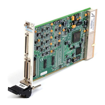
Figure 1. PCI, PCI Express, and PXI R Series Devices
Connectivity Options
Driver, for information on R Series software
section.
Advertisement
Table of Contents

Related Manuals for National Instruments PCIe-784 R Series


Summary of Contents for National Instruments PCIe-784 R Series
- Page 1 Getting Started with R Series Multifunction RIO This document explains how to install and configure National Instruments PCI/PXI-781xR, PCI/PXI-783xR, PCIe/PXI-784xR, and PCIe/PXI-785xR, referred to collectively as NI 78xxR devices. This document also contains a tutorial section that demonstrates how to begin taking a measurement using a LabVIEW FPGA example VI.
- Page 2 . In LabVIEW 8.0 or later, you can also view ni.com/manuals the LabVIEW Manuals directory that contains these documents by selecting Start»All Programs» National Instruments»LabVIEW»LabVIEW Manuals. Step 2. Install the Device, Accessories, and Cables This section describes how to unpack and install the NI PCI/PCIe/PXI-78xxR devices.
- Page 3 NI PXI-78xxR, insert the device into the PXI slot. Use the injector/ejector handle to fully inject the NI PXI-78xxR into place. NI PCI/PCIe-78xxR Device PCI/PCI Express System Slot PC with PCI/PCI Express Slot Figure 2. Installing an NI PCI/PCIe-78xxR Device © National Instruments Corporation Getting Started with R Series Multifunction RIO...
- Page 4 For the NI PCI/PCIe-78xxR, replace the computer cover, if applicable. Plug in and power on the computer or PXI chassis. To confirm that your device is recognized, complete the following additional steps: Select Start»All Programs»National Instruments»Measurement & Automation to open Measurement & Automation Explorer (MAX). Expand Devices and Interfaces.
-
Page 5: Step 3. Connect Signals
DGND DIO5 DGND DIO4 TERMINAL 1 TERMINAL 34 DGND DIO3 TERMINAL 35 TERMINAL 68 DGND DIO2 DIO1 DGND DGND DIO0 Figure 4. NI 781xR Connector Pin Assignments and Locations © National Instruments Corporation Getting Started with R Series Multifunction RIO... - Page 6 68 34 DIO39 DIO38 68 34 AI0– AI0+ DIO37 67 33 DIO36 67 33 AIGND1 AIGND0 TERMINAL 68 DIO35 66 32 DIO34 AI1+ 66 32 AI1– DIO33 65 31 DIO32 AI2+ 65 31 AI2– TERMINAL 34 DIO30 DIO31 64 30 64 30 AIGND2 AIGND3...
-
Page 7: Connectivity Options
Connectivity Options Accessing the signals on the I/O connectors requires at least one cable and one signal accessory. Table 1 summarizes the National Instruments connectivity options available for use with the NI 78xxR device. Table 1. R Series Connectivity Options... - Page 8 Step 4. Using Your NI 78xxR Device with a LabVIEW FPGA Example VI (NI 783xR/784xR/785xR Only) The NI-RIO driver installation includes a variety of example projects to help get you started. This section demonstrates how to use an existing LabVIEW FPGA example project to take an analog input measurement with the NI 783xR/784xR/785xR device.
- Page 9 R Series device. To view real-world data, wire a signal source or voltage source to AI0+ (RMIO pin 68) and AI0– (RMIO pin 34) of the terminal block. © National Instruments Corporation Getting Started with R Series Multifunction RIO...
- Page 10 Adding Analog Output to the FPGA Application To expand the LabVIEW FPGA application to include analog output, complete the following steps: On the block diagram of Analog Input (FPGA).vi, insert a new frame between the first and second frames of the Flat Sequence structure by right-clicking the divider between the first two frames and selecting Insert Frame from the shortcut menu, as shown in the following figure.
- Page 11 Read/Write Control. Click the section labeled Unselected and change it to AO Voltage. Right-click the AO Voltage (bits) terminal and select Create»Control, as shown in the following block diagram. © National Instruments Corporation Getting Started with R Series Multifunction RIO...
-
Page 12: Where To Go From Here
To access this document, refer to . In LabVIEW 8.0 or later, you can ni.com/manuals also view the LabVIEW Manuals directory that contains this document by selecting Start» All Programs»National Instruments»LabVIEW»LabVIEW Manuals. Getting Started with R Series Multifunction RIO ni.com... -
Page 13: Additional Resources
National Instruments corporate headquarters is located at 11500 North Mopac Expressway, Austin, Texas, 78759-3504. National Instruments also has offices located around the world to help address your support needs. For telephone support in the United States, create your service request at and follow the calling instructions or dial 512 795 8248. - Page 14 National Instruments, NI, ni.com, and LabVIEW are trademarks of National Instruments Corporation. Refer to the Terms of Use section on ni.com/legal for more information about National Instruments trademarks. Other product and company names mentioned herein are trademarks or trade names of their respective companies. For patents covering National Instruments products/technology, refer to the appropriate location: Help»Patents in your software, the patents.txt file on your...
Need help?
Do you have a question about the PCIe-784 R Series and is the answer not in the manual?
Questions and answers