
Related Manuals for Avipas AV-3207


Summary of Contents for Avipas AV-3207
- Page 1 Model: AV-3207 4D Serial & IP Joystick Controller User Manual V1.1 Please read this user manual thoroughly before using. www.avipas.com...
-
Page 3: Table Of Contents
1. Security Guidance ......................1.1 Cautions ............................2. Check Before Using ......................2.1 Packing List ..........................2.2 The Wiring ..........................2.3 Bottom Dialing Switch ......................3. Keyboard Description ....................3.1 Functional Features ........................3.2 Technical Specifications ......................3.3 Product Dimension ...................... -
Page 4: Security Guidance
1.1 Cautions Preface: This manual introduces the functions, technical specifications and operations of the serial/IP controller. Prior to installation and usage, please read the manual thoroughly. Precautions: This product can only be used in the specified conditions in order to avoid any damage to the controller: 1. -
Page 5: Check Before Using
2.1 Packing List When unpacked, check if all supplied accessories are included: Control keyboard ········································································ 1PCS Power Adapter ············································································ 1PCS Power Cord ··············································································· 1PCS RS232 Cord ··············································································· 1PCS User Manual ·············································································· 1PCS 2.2 Wiring 2.3 Bottom Dialing Switch Bottom dial control Mode SW-1 SW-2... -
Page 6: Keyboard Description
3.1 Product Features: 1. Support multiple network interfaces, including RS232, RS422 and RS485. 2. Supports VISCA Serial, Pelco-P, Pelco-D, VISCA over IP, VISCA TCP, VISCA UDP, ONVIF, and NDI (optional) protocols. 3. Equipped with seven camera shortcut control buttons. 4. Support button keys backlight. 5. -
Page 7: Product Dimension
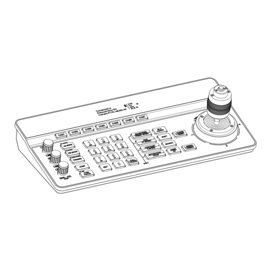
3.3 Product Dimension : 3.4 Interface Description : 1. Lock Port 5. Ethernet Port 9. Button 2. Type-C Upgrade Interface 6. Power Input 10. Joystick 3. RS232 Interface 7. Indicator light 11. Display screen 4. RS485 Interface 8. Knob 12. Dial switch... -
Page 8: Display Screen
3.5 Display Screen : 3.6 Button Function: 3.6.1 Shortcut Selection Area 【 CAM1 】 ~ 【 CAM7 】 Select the corresponding camera. 3.6.2 Adjustment Knob and 3A Setting Area 【 AE MODE 】 When the "AUTO" indicator light is on, the controller is under auto exposure mode. - Page 9 switch between Manual/Shutter/Iris/Gain mode. The knobs on the left side can be used to adjust parameters for Shutter, Iris, B/R Gain and Brightness. 【 WB MODE 】 When the "AUTO" indicator light is on, the controller is under AUTO/ATW mode. When the "AUTO" indicator light is off, the controller can switcher between Manual/Indoor/Outdoor/Sodium lamps/Fluorescent lamps modes.
- Page 10 【 TRIGGER 】 In One-push mode ("WB PUSH" light is on), the automatic white balance will turn on. 【 AF/MF 】 The "AF" indicator light will turn on under Auto Focus mode. Otherwise, the controller is under Manual Focus mode. Focus +/- can be adjusted by the third knob on the left side of the keyboard.
- Page 11 zoom speed. 【- SATURATION + / - ZOOM +】 Adjust the saturation. / Adjust the camera lens zoom. Note: Press the SHIFT button to switch between parameter setting mode and speed setting mode. The screen will display “S” when SHIFT is pressed. When "S"...
- Page 12 【 Zoom +】 Turn the joystick clockwise to zoom in. 【 Zoom -】 Turn the joystick counterclockwise to zoom out. 【 Lock 】 When controlling the camera and press the "lock" button, the camera will keep rotating in previous moving direction until the set lock time is exceeded or the camera rotates to the limit position.
-
Page 13: Menu Setting
4.1 Keyboard Menu Instructions: Long press CMENU/KMENU button to open the keyboard menu; Move the joystick Up or Down to view the menu options; Right to enter submenu; Left to return to the previous page. Note: Short press CMENU/KMENU can also return to the previous page; numeric keys 0~9 can set the corresponding parameters in some sections. -
Page 14: Wiring Diagram
5.1 Connection in network mode: 5.1.1 The keyboard controller connects with camera through PoE switch: In the same LAN, set the same network segment, correct protocol, IP address and port number, then you can control the camera. 5.1.2 The keyboard controller connects with camera directly: Connect the controller with camera directly via Ethernet cable, set the same network segment, correct protocol, IP address and port number, then you can control the camera. -
Page 15: Connection In Rs232 Mode
5.2 Connection in RS232 mode: Connect the controller with camera via RS232 cable, set correct protocol, address and baud rate, then you can control the camera. Line Sequence : Connect the controller with camera via RS232 cable. Connect controller pin 1 RXD with camera input interface TXD; connect controller pin 2 TXD with camera RXD;... -
Page 16: Connection In Rs485 Mode
Line Sequence : Use the RS422 connection. Let the controller pin 1 TXD + connects to the camera's RXD-, the controller pin 2 TXD - connects to the camera's RXD +, the controller pin 3 RXD + connects to the camera's TXD -, the controller pin 4 RXD - connects to the camera's TXD+. -
Page 17: Cascade In Rs232, Rs422, Rs485 Mode
Line Sequence : Use the RS485 connection. Let the controller pin 1 TXD + connected to the camera RXD-, the controller pin 2 TXD- connected to the camera RXD +. 5.5 Cascade in RS232, RS422, RS485 mode : Connect the cameras in daisy chain as shown below: Line Sequence :... - Page 18 with output port of second camera. Set correct protocol, address, baud rate, then you will be able to control the cameras.
-
Page 19: Web User Interface
PC. (For full instruction about how to access controller via IP, please refer to How-to material in our website: www.avipas.com). Open a browser, enter controller’s IP address in the address bar (default: 192.168.1.180). Login with default username and password: admin/admin. -
Page 20: Network Parameter
6.3 Ethernet Parameter Set the network parameters of the controller, including DHCP switch, IP Address, Netmask, Gateway, DNS, HTTP Port. 6.4 Firmware Upgrade The current firmware version will display on the screen. For firmware upgrade, please choose ‘select file’ and upload corresponding firmware files. -
Page 21: Account
6.6 Account Set login account and password of the controller. -
Page 22: Frequently Asked Questions
Frequently Asked Questions Description Solution Check if the Ethernet cable is connected properly. Check whether the camera supports corresponding protocol. Check whether the connection status icon display on the screen. If Cannot control the camera in the camera connected successfully, the icon " "... - Page 23 Thank you for your interest in the products of AVIPAS Inc. This Limited Warranty applies to this 4D Serial & IP Joystick Controller purchased from AVIPAS Inc. This Limited Warranty covers any defect in material and workmanship under normal usage within the Warranty Period.
- Page 24 Contact Details: AViPAS Inc. Address: 1700 Wyatt Drive, Suite #3, Santa Clara, CA 95054, United States Phone: 1-844-228-4727 Fax: (408) 228-8438 Email: info@avipas.com Website: http://www.avipas.com...
Need help?
Do you have a question about the AV-3207 and is the answer not in the manual?
Questions and answers