
Related Manuals for Avipas AV-3106


Summary of Contents for Avipas AV-3106
- Page 1 Model: AV-3106 Keyboard Controller User Manual V3.01 (English) Please read this User Manual throughout before using. www.avipas.com...
-
Page 2: Table Of Contents
CONTENTS 1. Summary ----------------------------------------------------------------------------------------------------- 1 1.1 Notice -------------------------------------------------------------------------------------------------- 1 1.2 Functions and characteristics ------------------------------------------------------------------------- 1 1.3 Technical data ------------------------------------------------------------------------------------------ 1 2. Keyboard Connections ------------------------------------------------------------------------------------ 2 2.1 Interface instructions --------------------------------------------------------------------------------- 2 2.1.1 RS422 and RS485 ------------------------------------------------------------------------------ 2 2.1.2 Power supply port ---------------------------------------------------------------------------- 2 2.1.3 EIA RS232 interface ------------------------------------------------------------------------- 2 2.1.4 RJ45 interface -------------------------------------------------------------------------------- 2 2.2 DIP switches settings --------------------------------------------------------------------------------- 3... - Page 3 4.3 Alarm box control ---------------------------------------------------------------------------------- 13 4.3.1 Set the alarm input channel and the alarm spot ------------------------------------------ 13 4.3.2 Set alarm ON/OFF status and reset alarm time ------------------------------------------- 13 4.3.3 Reset the alarm input manually ------------------------------------------------------------ 14 4.3.4 Resume factory default settings ---------------------------------------------------------- 14 4.4 Protocol settings ------------------------------------------------------------------------------- 14 4.4.1 Pelco matrix model ------------------------------------------------------------------------- 14 4.4.2 Direct control model ------------------------------------------------------------------------ 14...
-
Page 5: Summary
1. 1 Notice Please read this manual thoroughly before use, ● and keep it handy for future reference. Do not use or store AV-3106 in the environment ● where the product is exposed to rainwater, moisture vapor, salty water, oil, etc. -
Page 6: Keyboard Connections
Connection 2. Keyboard Connections 2.1 Interface instructions 2.1.3 EIA RS232 interface AV-3106 equipped with kinds EIA RS232 interface is used to expand the communication interfaces: RS232, RS422, RS485, functions to control the menu handler, DVR, PC and so RJ45. The user can find them on the back of the keyboard. -
Page 7: Matrix Connections
Connection Matrix connection 1. RJ45 local connection: the distance between the The keyboard can control matrices for PELCO keyboard and the matrix is less than 7.6m. CM6700 and CM6800. In order to introduce the 2. RJ45 interface is powered by 12VAC, which can connection between the keyboard and the matrix, take at the same time power the keyboard which is NOTICE... -
Page 8: Connect To A Dome Directly
Connection Connect to a dome directly Connect to a DVR The user can connect the keyboard to a dome via a The keyboard can be connected to a DVR and a dome RS485 cable for direct control. Make sure that keyboard via RS422 interface. - Page 9 Connection 2.6 Connect the keyboard in the system The user can use the keyboard to control the alarm box, and to connect the dome via the alarm box. Please see the alarm box user manual for more details regarding the connections. Every alarm box only can connect to one dome camera.
-
Page 10: Keyboard Operation Manual
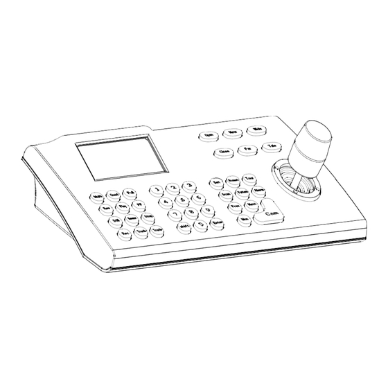
Connection Numeric zone Function Joystick DVR controlling Lens Controlling Picture 3-1.1 3. Keyboard Operation Manual 3.2 LCD This section mainly describes the operations of LCD is used to display the basic information of the keyboard. Notice that different systematic platforms may keyboard, including the keyboard model, keyboard ID, object not always have the same operation, and for particular camera, object monitor ID, baud rate, etc. -
Page 11: Change Object Dome
Connection Magnification control: Press 【Tele】 to get a higher ● Tilt the joystick to any direction, and the dome camera magnification. Let go to stop. will rotate to the corresponding direction. At the same Press 【Wide】 to get a lower magnification. Let go to stop. time, LCD displays the information at the lower right corner: “”, which respectively reflects tilt up, Magnification can also be controlled by rotating the joystick. -
Page 12: Tour
Connection Run pattern:【N】 + 【Pattern】 ● Input pattern NO. (1-4), then press 【 Pattern】, the corresponding pattern will run. 3.6.4 Tour Run tour:【N】 + 【Tour】/【Tour】 Press tour number, then press 【Tour】, run tour. If system has only one tour path, then press only 【Tour】... -
Page 13: Call The Dome Main Menu
Connection 3.7 Call the dome main menu When the keyboard is working in Pelco matrix mode 【9】+【5】+【Preset】: call the main menu of (refer to 2.2 DIP switches settings), it can control the dome or the monitor via matrix. object dome, and the menu will display on the object NOTICE Only in Pelco matrix mode, can the keyboard monitor. -
Page 14: Keyboard Menu
Connection 2. Press【1】to enter Keyboard setup 4. Keyboard Menu The LCD screen is shown below (see Picture 4.1.1- The keyboard menu controlling Press 【Set】, and hold it for 2 seconds, the keyboard 1. Set keyboard ID main menu will show on the LCD (see Picture 4.1-1). The 2. -
Page 15: Joystick Calibrations
Connection Press 【1】 again to enable the password. The LCD 4.1.2 Set keyboard baud rate screen will show the “Success” message, which means Enter menu, the LCD screen will show the main accessing the main menu requires a password; Press 【2】 menu (sees Picture 4.1.1-1). -
Page 16: Multi-Keyboard Connection Settings
Connection 4.2 Dome function settings Enter the main menu, and press 【2】 to enter Dome Joystick is free then setup. The LCD screen will show as below. Press Enter 1. Set dome preset Picture 4.1.4-1 2. Set dome scan Press 【 Enter】 to complete the operation. 3. -
Page 17: Pattern Scan
Connection 1. Set left limit Press 1 to start 2. Set right limit Press 0 to stop 3. Run scan press Prev to go back press Prev to go back Picture 4.2.3-2 Press 【3】, the dome will continuously repeat Picture 4.2.2-1 moving along the path that has been recorded. -
Page 19: Alarm Box Control
Operation 4.3 Alarm box control 1. Port No (1-8) The keyboard can be used to control the 2. Status (1/0) alarm box for the following operations: 3. Preset point (1-80) • It can set the state of the input alarm signal and the preset position number of that input channel. -
Page 20: Reset The Alarm Input Manually
Operation 4.3.3 Reset the alarm input manually 4.4 Protocol settings Enter the Alarm box setup menu, and the LCD Enter the main menu, and the LCD screen will screen will show as Picture4.3.1-2. Press【3】 to enter show as Picture4.3.1-1. Press 【3】to enter the Alarm acknowledge to reset the alarm input protocol setting, and the LCD screen will show as Channel manually. -
Page 21: Exit Keyboard Menu
Operation 4.5 Keyboard message display There are two different protocols: DVR and special DVR (SDVR). The user may choose one according to the Enter the main menu, and press 【5】 to enter About usage environment. Press 【Enter】 or move the joystick keyboard menu to check the keyboard information on the rightwards to confirm. -
Page 22: Appendix
Appendix Problems in practice 5.1 RS485 bus line basics In practice, the user usually adopts a star Characteristics of RS485 bus line configuration, and in this case, terminal resistors must As specified by RS485 standards, RS485 bus line is a locate at the two devices that are farthest away (see half-duplex data transmission cable with characteristic Picture 5-1.3 device1# and 15#). -
Page 23: Keyboard Shortcut Operation Manual
Appendix 5.2 Keyboard shortcut operation manual Working Operation object Shortcut Function Mode 【N】 + 【Cam】 Input the object dome id number, then press 【Cam】 to select the High speed dome dome. Press 【Tele】 to increase the magnification of lens. 【Tele】 High speed dome Press 【Wide】... -
Page 24: Keyboard Menu Index
Appendix 6. Keyboard Menu Index... -
Page 25: Maintenance Service Terms
Appendix 7. Maintenance service terms 1. Range of warranty AViPAS warrants its new product against defects in materials and workmanship for a period of ONE (1) ● YEAR from the date of original invoice. Within three months after the 1-year warranty, if the product is noticed to have the same malfunction as before ●... - Page 26 Maintenance Copyright Notice All contents of this manual, whose copyright belongs to our Corporation cannot be cloned, copied or translated without the permission of the company. Product specifications and information which were referred to in this document are for reference only. We may alter the content at any time and without prior notice. Contact Details: SWIT Electronics USA, LLC Address: 3350 Scott Blvd.
- Page 27 Keyboard Controller Users Manual Version V3.01 Manufacturer: Distributed by: AViPAS Inc. SWIT Electronics USA, LLC www.avipas.com www.swit.us 4300 Stevens Creek Blvd. Suite 230 3350 Scott Blvd. 61-02 San Jose, CA 95129 Santa Clara, CA 95054 (408) 983-0866 1-844-228-4727 (408) 228-8438...
Need help?
Do you have a question about the AV-3106 and is the answer not in the manual?
Questions and answers