Table of Contents
Advertisement
Quick Links
Technical Manual
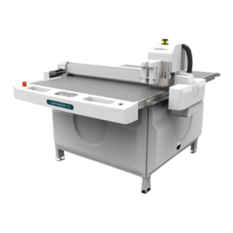
Kongsberg XE and i-XE Systems
with GC900sm Controller
This manual contains a technical description of the
GC900sm Controller based Kongsberg Cutting System.
The purpose of this manual is to offer documentation necessary for service personnel.
Note
We remind you that only the Esko-Graphics staff, or persons
having received an appropriate training, are allowed to handle,
manipulate or do running repairs on the machines.
______________________________________
A Publication of: Esko-Graphics Kongsberg AS
Copyright © 1984-2009 Esko-Graphics Kongsberg AS.
This copyright does not indicate that this work has been published.
All rights strictly reserved. Reproduction or issue to third parties in any form
whatever is not permitted without written authority from the publisher.
Esko-Graphics reserves the right to change specifications without notice.
Document number: D3018
Status: 091012
Esko-Graphics Kongsberg AS
www.esko.com
P.O.Box 1016, N-3601 Kongsberg, Norway
Tel: +47 32 28 99 00 Fax: +47 32 28 85 15 / 32 28 67 63
Advertisement
Table of Contents

Related Manuals for Esko Kongsberg XE


Summary of Contents for Esko Kongsberg XE
- Page 1 The purpose of this manual is to offer documentation necessary for service personnel. Note We remind you that only the Esko-Graphics staff, or persons having received an appropriate training, are allowed to handle, manipulate or do running repairs on the machines.
-
Page 2: Table Of Contents
Technical Manual Kongsberg XE/i-XE 1. TABLE OF CONTENT 1. TABLE OF CONTENT ........................2 2. SYSTEM DESCRIPTION ........................ 5 ONGSBERG TABLES AN OVERVIEW ................5 PC ........................6 RONT 2.2.1 Hypertreading........................6 2.2.2 Power save ..........................6 ? ..............6... - Page 3 Technical Manual Kongsberg XE/i-XE 2.9.17 Tool selection........................27 2.9.18 Tool identifier........................27 2.9.19 Laser pointer........................27 2.9.20 Camera..........................27 2.10 F USES .............................. 28 2.10.1 MPU fuses..........................28 2.10.2 Motor fuses.......................... 29 2.10.3 Vacuum motor overload protection ................30 2.11 XE S...
- Page 4 Kongsberg AS does not warrant, guarantee or make any representations regarding the use, or the results of the use of the system or the information contained herein. Esko-Graphics Kongsberg AS shall not be liable for any direct, indirect, consequential or incidental damages arising out of the use or inability to use the system or the information contained herein.
-
Page 5: System Description
Technical Manual Kongsberg XE/i-XE 2. System description Kongsberg XE/i-XE tables, an overview RS232C Carriage Input Program File MAP, HPGL,DXF Operator Panel Front End PC Cutting Table The Cutting System consists of: • Base • Table top • Traverse • Carriage running along the traverse •... -
Page 6: The Front End Pc
Technical Manual Kongsberg XE/i-XE • SYSLOADMPC program for loading new/upgraded software into the GC900SM controller. The Front End PC For the system to run correctly, the Front End PC must be configured as follows: 2.2.1 Hypertreading • Hypertreading must be disabled. This setting is available from PC boot setup / performance menu. - Page 7 Technical Manual Kongsberg XE/i-XE Table positions 1558(61.3) Vacuum Area Working Area 800 x 1100 mm 31 x 43 inches 157(6.2) 172(6.8) () = inches (4.3) (4.9) (5.3)
-
Page 8: The Gc900Sm Control System
Technical Manual Kongsberg XE/i-XE The GC900sm Control System CU id Tool Id T1/T2 48V DC mon Zero Detect Y Tool Up Sns T1/T2 6/12A Material Detect Fan Control Warning Lamp 5x3/6A 3/6A 3/6A T1 Tool Rotation 3/6A T1 Tool u/d ( Reciproc. motor ) -
Page 9: Mpc800 Board Components And Settings
Technical Manual Kongsberg XE/i-XE 2.6.1 MPC800 Board components and settings LED1 LED2 Debug ( BDM ) RS232-2 +2.6V +3.3V +5VExt +15V -15V 2.6.2 Main Power Unit (MPU) Location: Hinged inside the front base frame. Connections: For a schematic on how to connect, see chapter ‘Electrical drawings’. -
Page 10: Servo Control Unit (Scu)
Technical Manual Kongsberg XE/i-XE Servo and vacuum on/off is controlled from MCU. In addition to the MCU board, one System id – board is mounted on the MCU SDB board inside the MCU unit. 2.6.4 Servo Control Unit (SCU) Location:... -
Page 11: 5X3/6 A Amplifier Board
Technical Manual Kongsberg XE/i-XE drawings’. Description: Performs servo control for Z and Tool Rotation. Encoder feedback from Y, Z and Tool Rotation is fed directly into this module. The analogue output from the TCU module is connected to 6/12 A amplifier for Y, and the 3/6 A amplifiers for Z and Tool Rotation. - Page 12 Technical Manual Kongsberg XE/i-XE A CAN network is used to communicate between the CU-modules. The network protocol is according to CAN specification 2.0. A twisted pair, connected as illustrated in the figure makes the network. A terminating resistor, 124 Ω, is required in each end of the network cable. The terminating resistor is available on the CU-board by connecting terminal S2 on the Signal Distribution board.
-
Page 13: Gc900Sm Power System
Technical Manual Kongsberg XE/i-XE GC900SM Power System 2.7.1 Mains The GC900SM controller is prepared for the following voltages: 115V + 10% 230V + 10% The voltage setting is made inside the MPU cabinet: • The +24 V power supply is wide range; no setting for input voltage is necessary. -
Page 14: Power Consumption
Technical Manual Kongsberg XE/i-XE Servo is switched off.. +10 % -10 % 170V 250V 270V 150V 190V 230V 210V 125V 135V 115V 105V Supply voltage 2.7.3 Power Consumption Description + 24 V (mA) Complete System, Servo Off Max System, Servo On, No... -
Page 15: Power On Cu-Modules
Technical Manual Kongsberg XE/i-XE 2.7.4 Power on CU-modules The following voltages are available on each CU-module: Voltage Purpose Supply to circuits inside the CU-module +5Vext. Supply for external devices, as Standard Panel, encoders +15V Supply for op.amps on the CU-module -15V Supply for op.amps on the CU-module... -
Page 16: Traverse Solution
Technical Manual Kongsberg XE/i-XE Traverse solution Two servomotors, X1 and X2, control the traverse position. One Y-motor controls the position of the Y-carriage. The angle of the traverse beam is automatically adjusted to obtain minimum friction. The proper angle is found during the execution of the ‘Register table size’ wizard. -
Page 17: Tool Solution
Technical Manual Kongsberg XE/i-XE Tool solution 2.9.1 The Tool Connection Board The Tool Connection Board is a signal distribution board for all signals going to the two tool positions T1 and T2. The board is connected to the TCU Signal distribution board through the flat cable... -
Page 18: Presscut Knife Tool, Pressure Controlled
Technical Manual Kongsberg XE/i-XE 2.9.2 PressCut knife tool, pressure controlled The Z-axis motor moves the tool head to a proper level and keeps a constant height relative to the tabletop (ttop.dat). Excenter radius is 4 mm; the distance between tool up and tool down is 4 Motor A provides ‘local’... -
Page 19: Crease Tool
Technical Manual Kongsberg XE/i-XE 2.9.4 Crease tool Motor A provides tool selection. Excenter radius is 10 mm; the distance between tool selected and tool not selected is 20 mm. The Z-axis provides tool up/down. Height control relative to the tabletop (ttop.dat). -
Page 20: Hi-Frequenc Vibracut Knife Tool
Technical Manual Kongsberg XE/i-XE 2.9.6 Hi-frequenc VibraCut knife tool The Z-axis motor provides tool up/down. The Z-axis position is controlled relative to the tabletop (ttop.dat). Motor A provides knife reciprocation. Different knife adapters allows for different knife types. A removable foot is available. The foot solution is preferable when cutting recycled materials. -
Page 21: The Varicut Tool
Technical Manual Kongsberg XE/i-XE 2.9.8 The VariCut tool The Z-axis motor is used for tool up/down. The Z-axis position is controlled relative to the tabletop (ttop.dat). The tool is floating by the foot on top of the material. The cutting depth is servo controlled. -
Page 22: The Measuring Foot
Technical Manual Kongsberg XE/i-XE 2.9.10 The Measuring foot The Measuring foot is used when: • Mapping the tabletop. • Measuring the material thickness. The sequence is as follows: An air cylinder moves the measuring 4(A) pin down 2(B) The Z-axis motor moves the tool down until the HMD sense signal is received. -
Page 23: Pressurized Air Adjustment For The Measuring Foot
Technical Manual Kongsberg XE/i-XE 2.9.11 Pressurized air adjustment for the measuring foot 2.9.11.1 MultiFunction units before May 2008 Separate air cylinders are used for the measuring foot and the ballpoint pen tool select movement. The air pressure for air cylinders is adjustable by a valve inside the Y carriage. -
Page 24: Tool Selection By Excenter
Technical Manual Kongsberg XE/i-XE Pressurized air in Pressurized air in Adjust each throttle until the movement up and down is smooth. Lock the adjustment using the locking nut. Note: As for the previous version of the MultiFunction unit, it is important to ensure that the measuring foot is down towards the housing when in down position. -
Page 25: Tool Selection And Pressure By Excenter
Technical Manual Kongsberg XE/i-XE 2.9.13 Tool selection and pressure by excenter Tool in The PressCut knife tool is equipped with a servo-controlled excenter. Tool up operation The excenter is used for tool selection and tool pressure as illustrated at left. -
Page 26: The Z-Axis
Technical Manual Kongsberg XE/i-XE 2.9.15 The Z-axis All tools are mounted on the Z-axis bracket. The common Z-axis movement provides tool up/down for all tools except the PressCut knife tool. 2.9.15.1 Zero reference for the Z - axis Zero reference for the Z - axis is the upper mechanical end stop. During the Table Zero sequence, the Z - axis will move upwards until the mechanical end stop is reached. -
Page 27: Tool Rotation
Technical Manual Kongsberg XE/i-XE 2.9.16 Tool rotation 2.9.16.1 General Tool rotation is provided by a Tool rotation motor controlled by one of the 5x3/6 A amplifiers located inside the TCU unit (Picture) For XE, there is a separate tool rotation motor inside each tool. -
Page 28: Fuses
Technical Manual Kongsberg XE/i-XE mounted on the front of the Multi-Function unit. 2.10 Fuses 2.10.1 MPU fuses GC800 MPU 2007 (32569006) F1 and F2: 115VAC: 10A 250V T 5x20mm Slow Blow (42448985) 230VAC: 5A 250V T 5x20mm Slow Blow (42448951) -
Page 29: Motor Fuses
Technical Manual Kongsberg XE/i-XE 2.10.2 Motor fuses This overview includes all fuses in the system: 6/12A T 8A 250V M14437 3/6A T 2A 250V RE036 3/6A T 0,5A 125V Tool sel. Fh 2224 T 0,5A 125V 3/6A Tool depth Amax 22... -
Page 30: Vacuum Motor Overload Protection
Technical Manual Kongsberg XE/i-XE 2.10.3 Vacuum motor overload protection Recommended cable Overload Eff. Recommended mains fuses dimensions Pump Part.no 3 x V relay setting A SAP 150 42428052 230V (Δ) SAP 150 42428052 400V (Υ) SAP 180 42428045 230V (Δ) -
Page 31: Xe Safety Solution
Technical Manual Kongsberg XE/i-XE 2.11 XE Safety Solution Safety system blocked schematic 2.11.1 DynaGuard with LE20 controller, detailed description 2.11.2... -
Page 32: Troubleshooting The Gc900Sm Controller
Technical Manual Kongsberg XE/i-XE 2.12 Troubleshooting the GC900SM controller When searching for errors in the controller, it is important to fully understand the principles of operation. This chapter describes some steps to be taken to locate the faulty module(s): • First of all, the communication between the PC and the MCU and the communication between CU-modules must be properly running. -
Page 33: Xe System Parameters
Technical Manual Kongsberg XE/i-XE 2.13 XE system parameters 2.13.1 System id definitions Defined system System Id SysId1 SysId2 SysId3 board, (tool) (traverse) (table) Part number XE10 Standard system 32552978 i-XE10 Standard system 32554206 XE32/54 Standard system 32556938 i-XE32/54 Standard system 32556946 2.13.2... -
Page 34: Tool Series Id Definitions
Technical Manual Kongsberg XE/i-XE 2.13.3 Tool series id definitions ToolId 02 Tool board switch Tool number setting ( Tool number ) Tool no 1 1 & 2 off Tool no 2 1 on & 2 off Tool no 3 1 off & 2 on Tool no 4 1 &... -
Page 35: Motor / Encoder Specifications
Technical Manual Kongsberg XE/i-XE 2.14 Motor / Encoder Specifications Moto Timing Screw Move- Total Motor part belt pitch ment Device Part no Function Motor type gear Enc. gear gear ratio ratio ratio Hi-force knife Tool RE36 34050807 42419960 12:36 tool... -
Page 36: Signal Lists
Technical Manual Kongsberg XE/i-XE 3. Signal lists Signals to/from CU-modules 4. Cables XE10/i-XE10 with LE20 safety relay... -
Page 37: Xe With Xl-Register
Technical Manual Kongsberg XE/i-XE 5. XE with XL-Register A separate user/service manual is available for XL-register, see ‘22464978 XL-register on XE’. 6. XE with I-Cut (i-XE) A separate user/service manual is available for i-XE, see ‘22464986 i-xe_service manual.doc’. -
Page 38: How To
Technical Manual Kongsberg XE/i-XE 7. How to... procedures Installation A separate Installation manual is available: 22465017 xe_installation Maintenance A separate Maintenance manual is available: 22465025 xe_maintenance Traverse beam / X-carriage fixture on xXE32/54 Warning: Be careful and use correct screws with correct gasket when fixing the... -
Page 39: Motor Assembly On Xe10/I-Xe10
Technical Manual Kongsberg XE/i-XE Motor assembly on XE10/i-XE10 Due to narrow space, care should be taken when mounting the X-motors: Traverse beam X encoder X gearbox X motor Avoid encoder cable facing downwards. Avoid motor brush housing facing downwards. Encoder cable should face upwards. -
Page 40: How To Remove X1/X2 Covers, Xxe10
Technical Manual Kongsberg XE/i-XE How to remove X1/X2 covers, xXE10 Remove the safety cover. Remove the bracket for the safety cover ( on one side only ). - Page 41 Technical Manual Kongsberg XE/i-XE Disconnect both photocell cables and remove one photocell as shown at left. Remove the two screws holding the safety shaft. Pull the safety shaft sideways out as shown. Remove the cover.
-
Page 42: How To Remove X1/X2 Gearbox, Xxe10
Technical Manual Kongsberg XE/i-XE How to remove X1/X2 gearbox, xXE10 Four screws as indicated at left fixes the gearbox to the traverse. The pinion gear is adjusted by lifting the gearbox up or down. To keep track of the gearbox position, an adjustment screw is available (below left). -
Page 43: How To Remove X1/X2 Covers, I-Xe32/54
Technical Manual Kongsberg XE/i-XE How to remove X1/X2 covers, i-XE32/54 After the cover on the traverse end has been removed, remove the safety cover as indicated at left. Remove the cables to the photo cells. Remove the 4 screws holding the cable guide and the photo cell bracket. -
Page 44: How To Remove The Y-Carriage Cover
Technical Manual Kongsberg XE/i-XE How to remove the Y-carriage cover Remove screws 1, 2, 3 and 4. Loosen the four screws 5. Lift the Y-carriage cover straight up. -
Page 45: How To Remove The Z-Axis Motor And Screw
Technical Manual Kongsberg XE/i-XE How to remove the Z-axis motor and screw Insert a stopper beneath the Z- carriage to avoid the carriage moving off the guides. For the same reason, remove the lifting spring. - Page 46 Technical Manual Kongsberg XE/i-XE Loosen the 4 screws in front holding the Z-axis nut. Loosen the Z-axis motor bracket. After removing the cables, the Z- axis motor together with the screw is loose.
-
Page 47: Gear Adjustment, Basic Principles
Technical Manual Kongsberg XE/i-XE 7.10 Gear adjustment, basic principles Inside each gearbox X1, X2 and Y, there are two gears that needs adjustment; between the motor pinion and the big tooth wheel and between the plastic pinion and the rack. -
Page 48: Motor Pinion Adjustment
Technical Manual Kongsberg XE/i-XE 7.11 Motor pinion adjustment 7.11.1 General Gear wheel Motor pinion Eccenter fixture The gear wheel (motor pinion) on the X and Y motor engages with a big-diameter gear wheel inside the gear box. The motor is mounted onto an eccentric bracket. -
Page 49: Y-Axis Motor Pinion
Technical Manual Kongsberg XE/i-XE 7.11.2 Y-axis motor pinion The Y-axis motor is easy accessible inside the Y-carriage. 7.11.3 X-axis motor pinion, XE10 and i-XE10 The X-axis motor is inside the traverse. You can see the motor pinion in the picture at left. -
Page 50: Rack Pinion Adjustment
Technical Manual Kongsberg XE/i-XE 7.12 Rack pinion adjustment 7.12.1 Adjusting X-axis rack pinion on xXE10 The main principle on these machines is to turn the gearbox around screw 5 in order to achieve correct gear tension. Use the adjustment screw 1 to keep track of the gearbox position. - Page 51 Technical Manual Kongsberg XE/i-XE Loosen the gear Stronger gear tension The X-axis rack pinion depth of engagement is adjusted by lifting/rotating the X-axis gearbox up or down. Procedure: • Slightly loosen the screws 2, 3, 4 and 5. • Use screw 1 to move the gearbox up or down.
-
Page 52: Adjusting X-Axis Rack Pinion On Xxe32/54
Technical Manual Kongsberg XE/i-XE 7.12.2 Adjusting X-axis rack pinion on xXE32/54 On these machines, the carriage and the gearbox are combined in one unit. Therefore, when adjusting the rack pinion gear, you have to move the whole carriage up or down. -
Page 53: Adjusting Y-Axis Rack Pinion On Xxe10/32/54
Technical Manual Kongsberg XE/i-XE 7.12.3 Adjusting Y-axis rack pinion on xXE10/32/54 The Y-axis rack pinion depth of engagement is adjusted by moving the Y-axis gearbox forward or backwards. Procedure: • Slightly loosen the screws 1, 2, 3 and 4. •... -
Page 54: Electrical Drawings, Index
Technical Manual Kongsberg XE/i-XE 8. Electrical drawings, index Part Detail Drawing # Rev. Mains Mains connection, Wiring diagram 255620 Main Switch Wiring diagram, XE10 256817 Main Switch Wiring diag. i-XE10 with i-Cut comp.stand 256646 Main Switch Wiring diag. i-XE10 with Kbg. comp.stand... -
Page 55: Mechanical Drawings, Index
Technical Manual Kongsberg XE/i-XE Part Detail Drawing # Rev. VariCut tool Tool Board Layout 256775 HF VibraCut tool Tool Board Layout 256890 Glue applicator Tool Board Layout 256777 Pen / HMD El schematic CU – board MPC800 Board layout X/Y amplifier 6/12 A... - Page 56 Technical Manual Kongsberg XE/i-XE Rulers Ruler mounting 404733 Traverse xe 406125_4 Traverse xe Traverse xe 406125_5 i-XE10 Belt mechanics fixture layout 405258 i-XE32 Belt mechanics fixture layout 406973 i-XE54 Belt mechanics fixture layout 406974...
-
Page 57: Appendix - Vacuum Zones
Technical Manual Kongsberg XE/i-XE 10. Appendix – Vacuum zones Standard vacuum Optional vacuum solution solution XE10 XE10 i-XE10 i-XE10 XE/i-XE32 XE/i-XE32 XE/i-XE54 XE/i-XE54 Illustrations: - This section is always on. - This section is selectable. The button configuration in the GUI is machine... -
Page 58: Appendix - Hour Counter And Maintenance Tracking
Technical Manual Kongsberg XE/i-XE 11. Appendix – Hour counter and maintenance tracking The hour counter system consists of the following elements: 11.1 Hour counter The hour counter summarizes the time when the system is running. It counts the time when the machine is actually running. -
Page 59: Maintenance Tracking
Technical Manual Kongsberg XE/i-XE 11.3 Maintenance tracking After system maintenance has been completed, the service engineer should update the Maintenance tracking information: Press the shortkey CTRL-ALT-M. The following dialog will appear: This dialog serves two purposes: • Specify next maintenance •... -
Page 60: Maintenance Warning Dialog
Technical Manual Kongsberg XE/i-XE 11.4 Maintenance warning dialog This is an example of the Maintenance warning dialog: 11.5 Maintenance reminder Once a month, the maintenance remainder page is displayed:... -
Page 61: Appendix - Friction Level Measurement
Technical Manual Kongsberg XE/i-XE 12. Appendix – Friction level measurement Measuring the friction level along X and Y has been introduced from XE-Guide version 9039. Measuring the friction is carried out as an addition to the Register table size function. - Page 62 Technical Manual Kongsberg XE/i-XE Frictiondata.txt My xe, friction level 1500 1000 I-X1+ I-X2+ I-Y+ I-X1- I-X2- I-Y- -500 -1000 -1500 Position File and graphic display of Frictiondata.txt in Excel.
Need help?
Do you have a question about the Kongsberg XE and is the answer not in the manual?
Questions and answers